Cisco ACI - Fabric Deployment 6.x
Hi Folks!! 😉 In this blog post I’ll explain you how to bring up a Cisco ACI Fabric with 6.x release and how to solve quick issues about it, let’s go!
Prerequisites
Bringing up a Cisco ACI fabric requires you some work before starting the job, I strongly suggest you to do not skip the following tasks:
-
Configure CIMC IP address for all the UCS servers
If you don’t have any idea on how to do that, here are three simple way to achieve it:-
Download a DHCP server program on your PC and connect your laptop to the CIMC port of the server. By doing this you will release an IP address to the server and then you can connect it via GUI and change it to the final IP address (or configure the DHCP server with the final pool already)
-
Configure a DHCP server on your switches and connect the CIMC ports to the switches. The DHCP server on your switches will release the necessary IP parameters to the UCS Server and then you’ll be able to connect to the CIMC GUI
-
Configure it via the UCS Console:
-
Connect the UCS Console cable to the server, a monitor and a keyboard
-
Power On the server
-
During the boot press F8 –> CIMC Setup
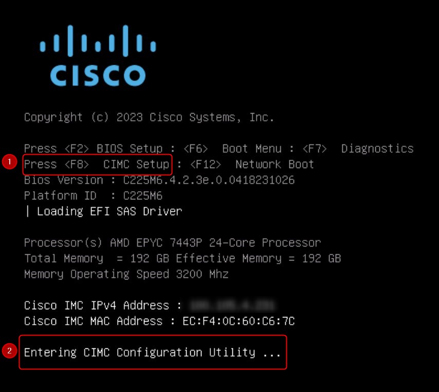
-
Configure the CIMC IP Address
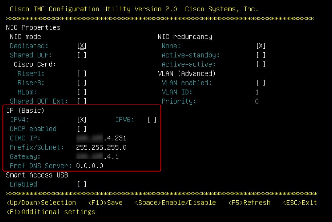
-
-
-
Map the device serial number to hostname, node ID, rack ID and rack unit
During the discovery phase Cisco ACI will show us the Serial Number of Leaves/Spines, so it’s important to map the Serial Number of the devices with the relative hostnames, here is a table template:Device Type Device Role Hostname SITE Device ID Site Row Rack RU Part number Serial number Software Version Note Controller APIC POD1-APIC-1 POD1 1 POD1 80 14 42 APIC-SERVER-L4 WZPxxxxxxJB 6.0(3d) Controller APIC POD1-APIC-2 POD1 2 POD1 81 12 42 APIC-SERVER-L4 WZPxxxxxxJ7 6.0(3d) Controller APIC POD1-APIC-3 POD1 3 POD1 80 14 40 APIC-SERVER-L4 WZPxxxxxxJE 6.0(3d) Spine SPINE POD1-SPINE-511 POD1 511 POD1 80 6 44 N9K-C9336C-FX2 FOXxxxxxxS3 16.0(3d) Spine SPINE POD1-SPINE-512 POD1 512 POD1 81 7 44 N9K-C9336C-FX2 FOXxxxxxxCR 16.0(3d) Border Leaf Fiber BLEAF POD1-BLEAF-101 POD1 101 POD1 80 8 44 N9K-C93600CD-GX FDOxxxxxx2N 16.0(3d) Border Leaf Fiber BLEAF POD1-BLEAF-102 POD1 102 POD1 81 9 44 N9K-C93600CD-GX FDOxxxxxx3H 16.0(3d) Access Leaf Fiber CLEAF POD1-LEAF-111 POD1 111 POD1 80 8 42 N9K-C93600CD-GX FDOxxxxxx3S 16.0(3d) Access Leaf Fiber CLEAF POD1-LEAF-112 POD1 112 POD1 81 9 42 N9K-C93600CD-GX FDOxxxxxx19 16.0(3d) BLEAR= Border Leaf –> Choose the name you prefer
CLEAF= Compute Leaf –> Choose the name you prefer -
Complete ALL the necessary cabling
Please, do not forget any cable. Any means Any, don’t skip it. Remember that in a Cisco ACI fabric you must connect all the Leaves with the Spines (no direct connections between leaves or spines) and all the APICs to the designated Leaves. I suggest you to fill a (or more) table with all the cabling done, here is a basic but common table template that you can use if needed:Device Site Row Rack Rack Unit Interface Device Site Row Rack Rack Unit Interface Transceiver (2x) Note POD1-SPINE-511 POD1 80 6 44 e1/1 POD1-BLEAF-101 POD1 80 8 44 e1/53 QSFP-40/100-SRBD POD1-SPINE-512 POD1 81 7 44 e1/1 POD1-BLEAF-101 POD1 80 8 44 e1/54 QSFP-40/100-SRBD POD1-SPINE-511 POD1 80 6 44 e1/2 POD1-BLEAF-102 POD1 81 9 42 e1/53 QSFP-40/100-SRBD POD1-SPINE-512 POD1 81 7 44 e1/2 POD1-BLEAF-102 POD1 81 9 42 e1/54 QSFP-40/100-SRBD POD1-SPINE-511 POD1 80 6 44 e1/11 POD1-CLEAF-111 POD1 80 8 40 e1/53 QSFP-40/100-SRBD POD1-SPINE-512 POD1 81 7 44 e1/11 POD1-CLEAF-111 POD1 80 8 40 e1/54 QSFP-40/100-SRBD POD1-SPINE-511 POD1 80 6 44 e1/12 POD1-CLEAF-112 POD1 81 9 38 e1/53 QSFP-40/100-SRBD POD1-SPINE-512 POD1 81 7 44 e1/12 POD1-CLEAF-112 POD1 81 9 38 e1/54 QSFP-40/100-SRBD Leaves: Usually the last 6 ports are dedicated to the fabric. During my projects I connect the leaves to the spines with the last two interfaces (53-54 usually)
Spines: The opposite of the Leaves, here you can use the first ports and not the last
APICs: It depends on your UCS model and which cards your pre-sales team put into the servers, but here is an example of VIC 1455 network card. Port-1 and port-2 is one pair, corresponding to eth2-1 on APIC and port-3 and port-4 is another pair, corresponding to eth2-2 on APIC. Only one connection is allowed for each pair. For example, you can connect one cable to either port-1 or port-2, and connect another cable to either port-3 or port:
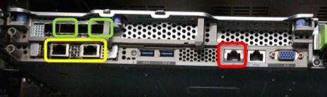
Green: Fabric ports. The port IDs are not from left to right but it’s from right to left, So port 1 is the first from the right, port 3 is the third from the right. I use port 1 and 3 because by default they are in different port-channels
Yellow: Out Of Band interfaces
Red: CIMC interface -
Fill the data in the following table. This is very important with all Cisco ACI releases (4.x/5.x/6.x) because they are common parameters that the fabric will ask us during the setup:
Name Description Default Value YOUR VALUE Notes Fabric Name Fabric domain name ACI Fabric1 XXXX-YYYYY Fabric ID Fabric ID 1 1 AS # Autonomous System Number -- XXXXX Choose the BGP AS for the Fabric Number of active controllers Cluster size 3 3 POD ID POD ID 1 1 Standby Controller Setup standby controller NO NO Controller ID Unique ID number for the active APIC instance. Valid range: 1–19 1 Standalone APIC Cluster APIC cluster not directly connected to the Fabric, but connected by a layer 3 inter-pod network (IPN) NO NO This feature is available only on Cisco APIC release 5.2(1) and later. Controller name Active controller name. apic1 XXX-YYY IP address pool for tunnel endpoint addresses Tunnel endpoint address pool. 10.0.0.0/16 X.X.X.X/16 This value is for the infrastructure virtual routing and forwarding (VRF) only. This subnet should not overlap with any other routed subnets in your network. If this subnet does overlap with another subnet, change this subnet to a different /16 subnet. VLAN ID for infrastructure network Infrastructure VLAN for APIC-to-switch communication including virtual switches -- XXX Reserve this VLAN for APIC use only. The infrastructure VLAN ID must not be used elsewhere in your environment and must not overlap with any other reserved VLANs on other platforms. IP address pool for bridge domain multicast address (GIPO) IP addresses used for fabric multicast 225.0.0.0/15 X.X.X.X/15 Valid range: 225.0.0.0/15 to 231.254.0.0/15, prefixlen must be 15 (128k IPs) IPv4/IPv6 addresses for the out-of-band management IP address that you use to access the APIC through the GUI, CLI, or API. -- X.X.X.X IPv4/IPv6 addresses of the default gateway Gateway address for communication to external networks using out-of-band management -- X.X.X.X Management interface speed/duplex mode Interface speed and duplex mode for the out-of-band management interface auto auto Strong password check Check for a strong password [Y] Password Password of the system administrator -- P4ssW0rd! This password must be at least 8 characters with one special character.
Perfect, now that you have filled all the tables, we can proceed in bringing up the fabric! 😉
Cluster Configuration
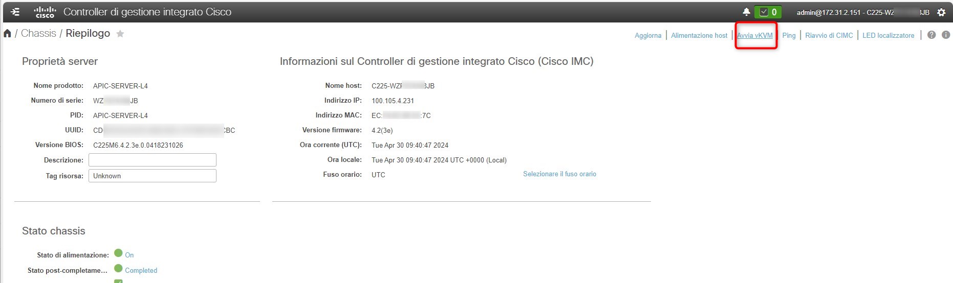
Connect to the first CIMC IP Address and login with the your credentials, the default one are: admin / password
Now, connect to the KVM interface:
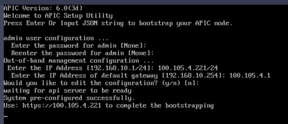
Press any key to continue and then you will see this prompt. Fill the requested field with the data that you’ve put into the previous table. When completed, the system will te you to use the http page of the APIC in order to complete the bootstrapping:
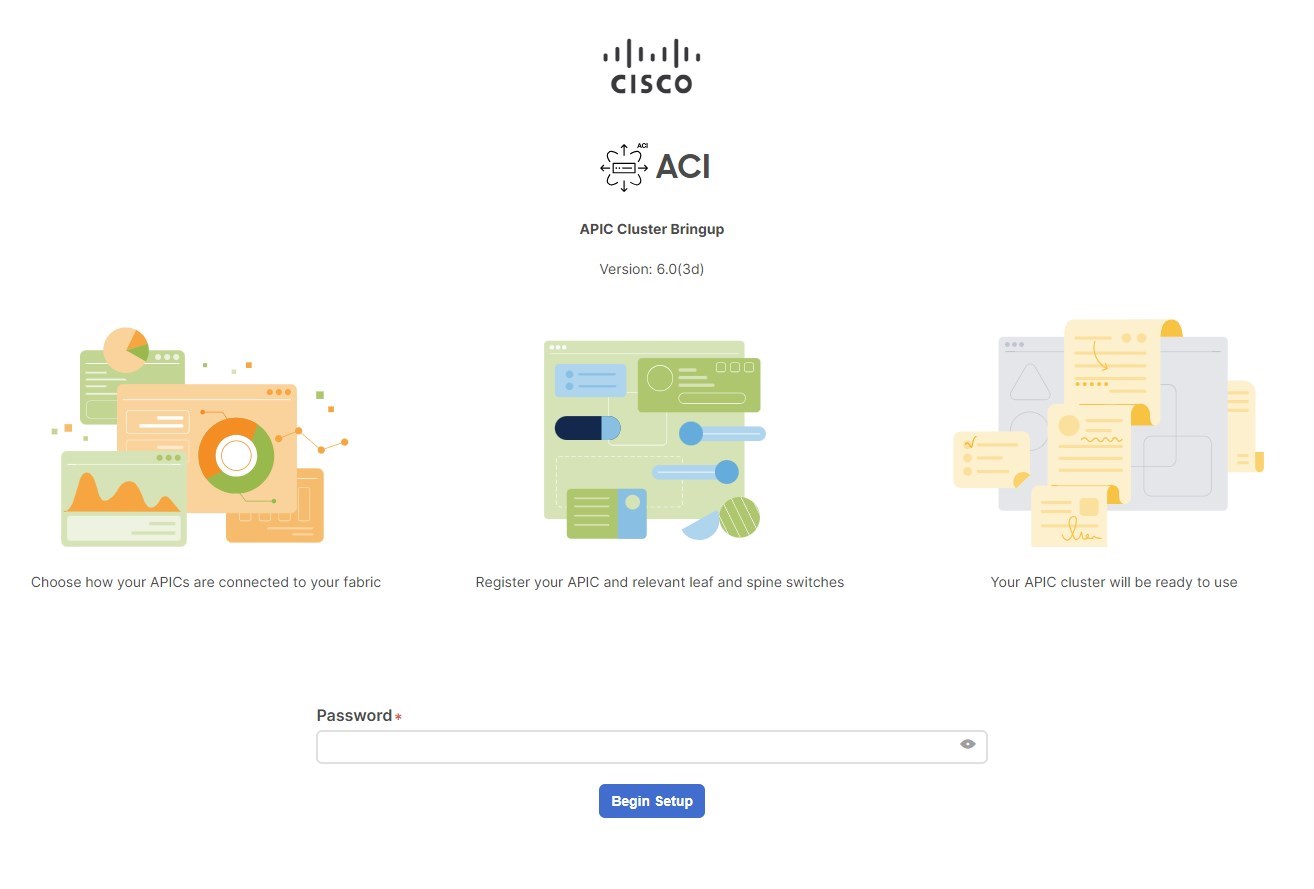
Great, lunch the APIC GUI: https://apic_ip_address and put the password
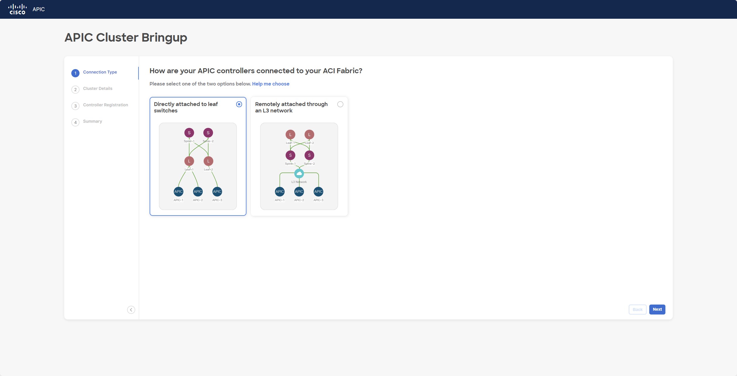
Based on your scenario, choose how the APICs are connected to the leaves:
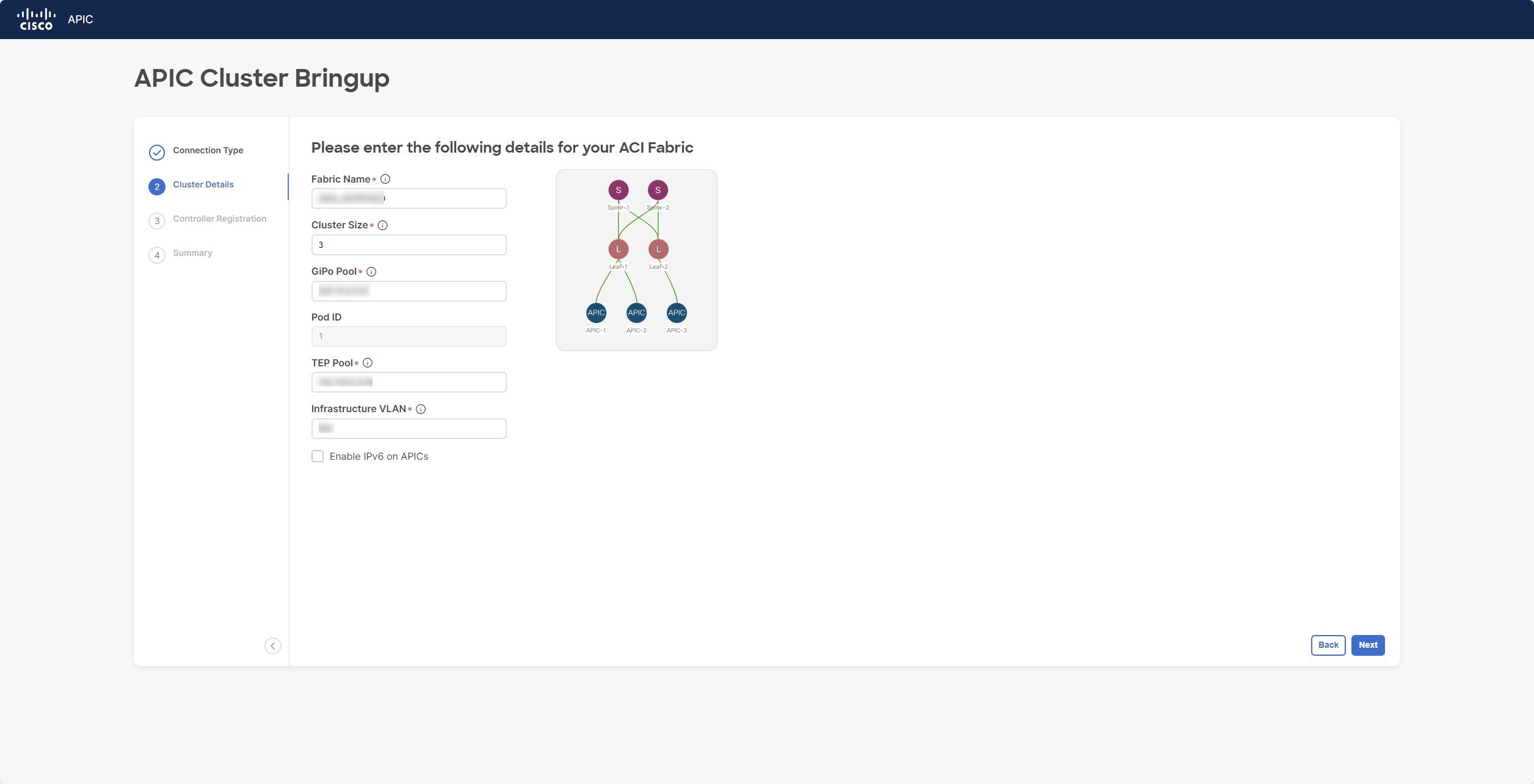
Then, based on the data in the tables, fill the following fields:
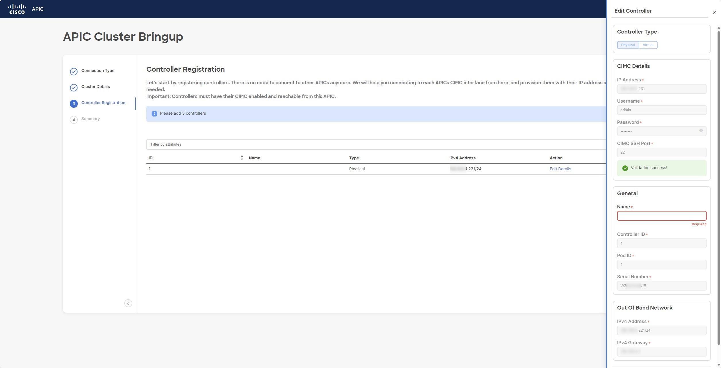
Perfect, now add the three controllers. Start with the CIMC address so the system will recognize the APIC firmware and auto-fill some parameters:
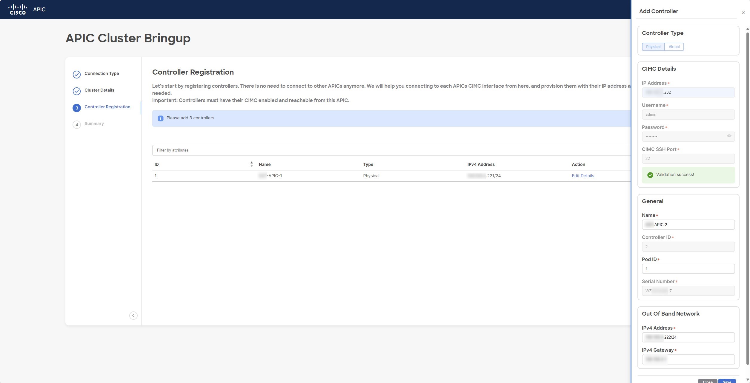
Proceed with APIC2
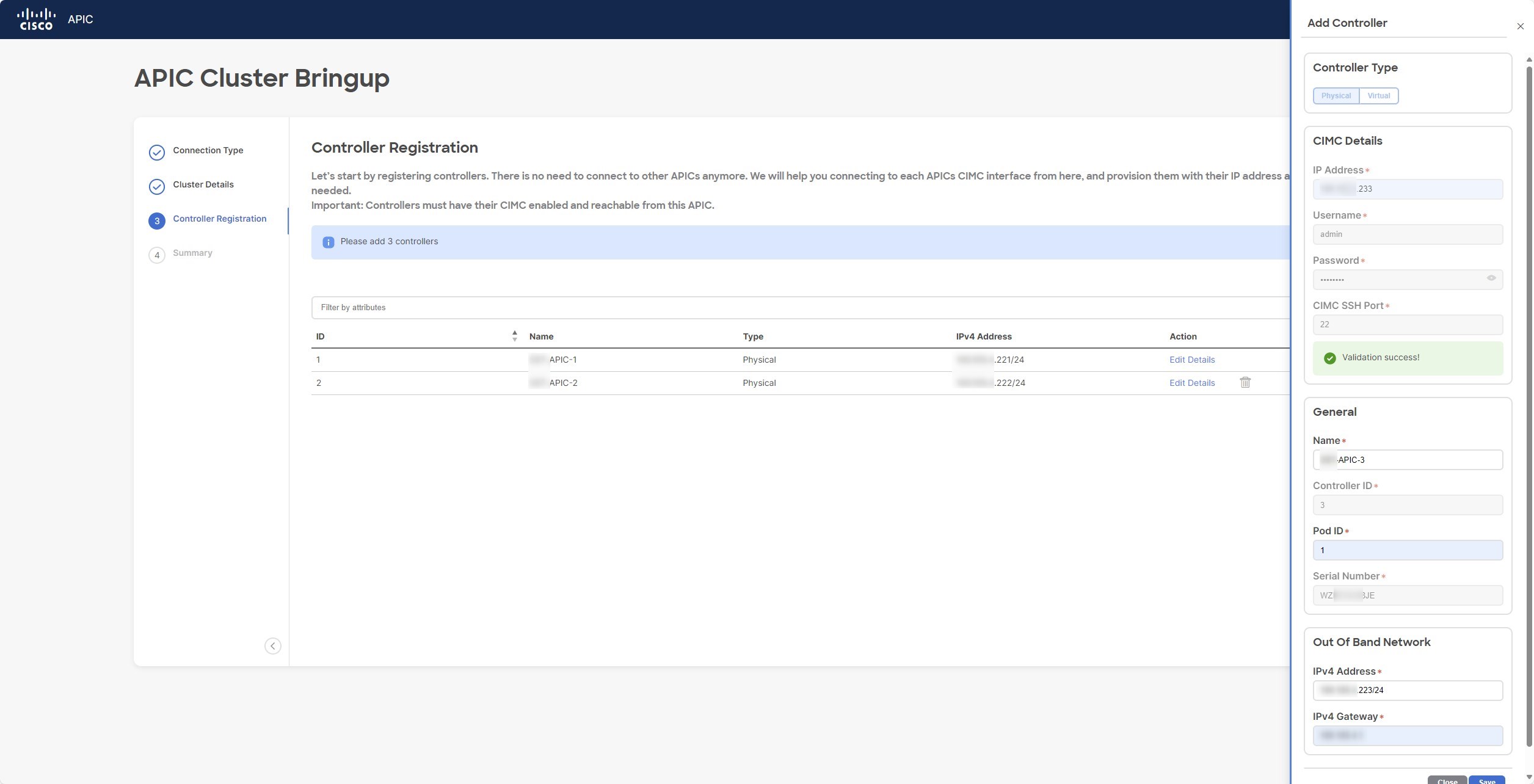
And then with APIC3
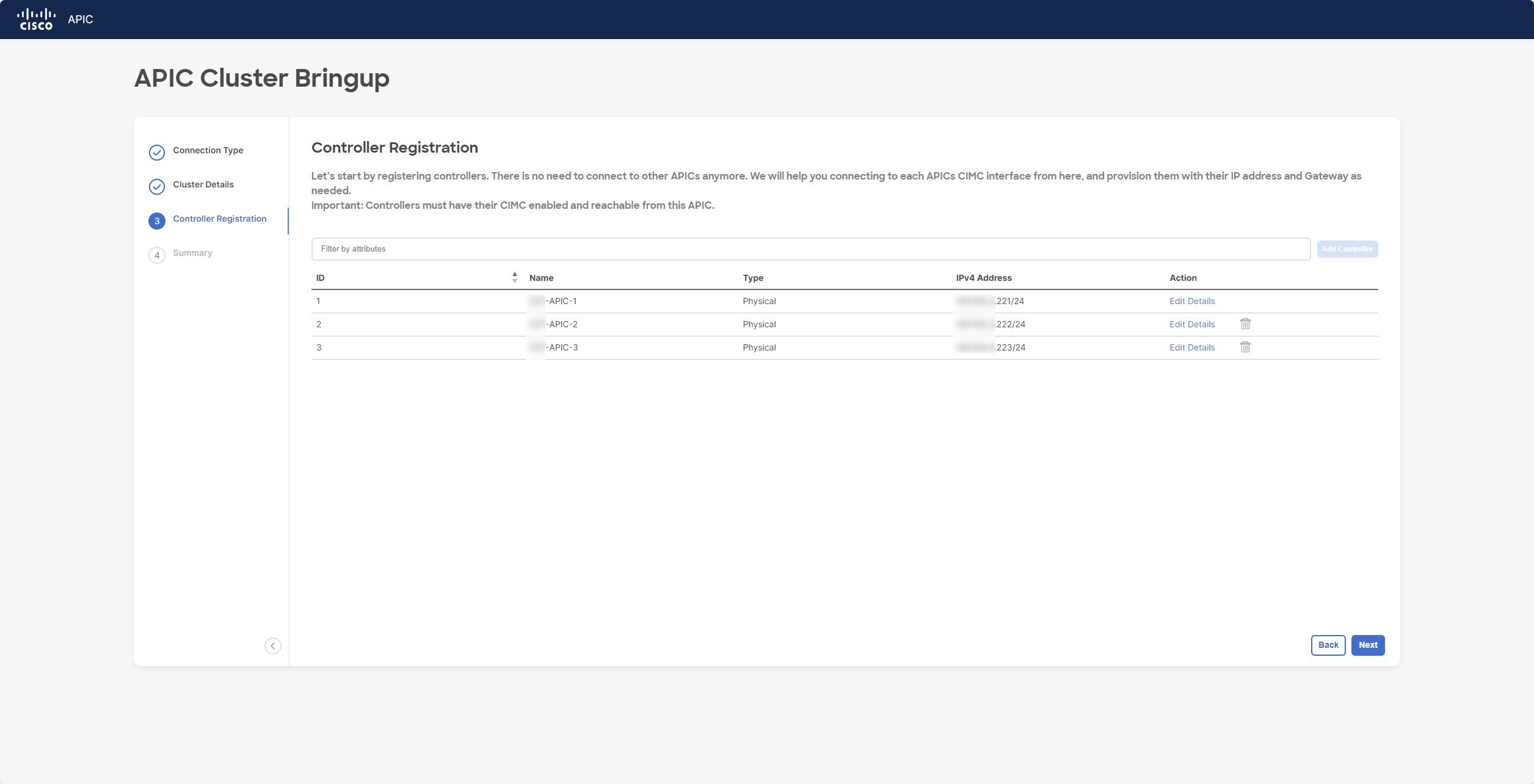
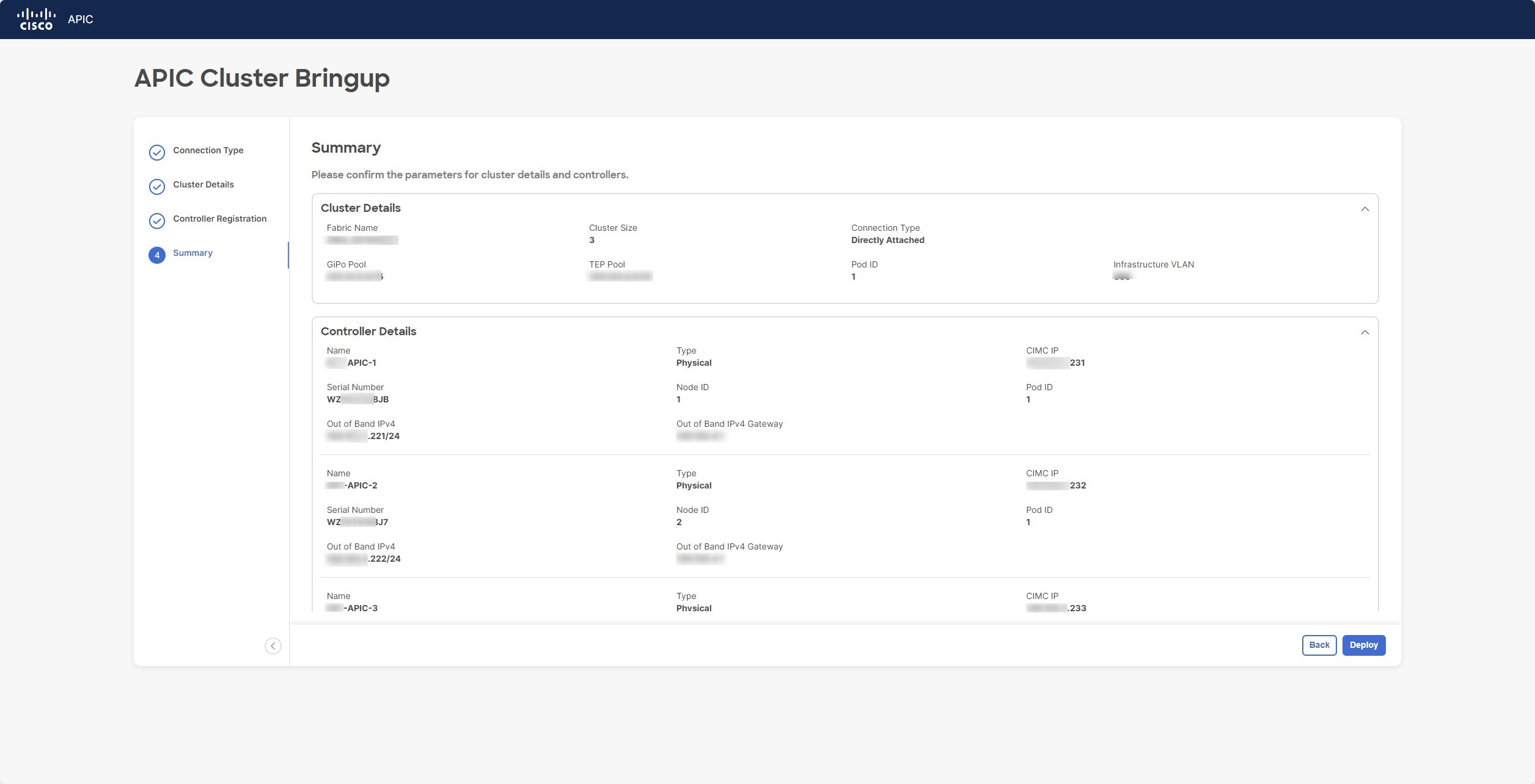
Here are the three APICs added to the cluster:
Now review all the information and then click on the “Deploy” button at the bottom of the page.
Great, if everything is ok now the bootstrapping starts and you can take a coffee 😊
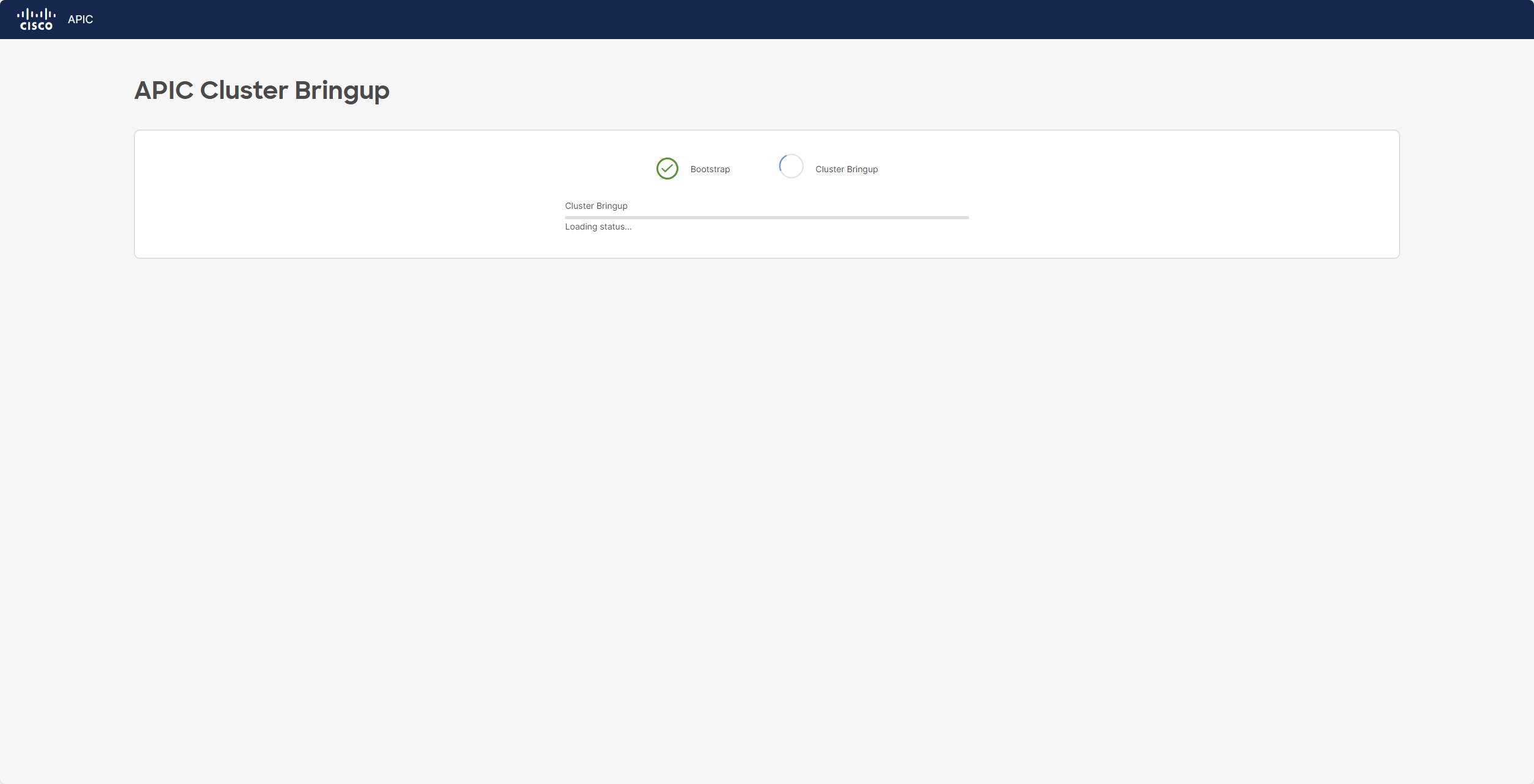
After 15m the first APIC should be up and running and you can proceed with the discovery phase!
Switch Discovery Phase
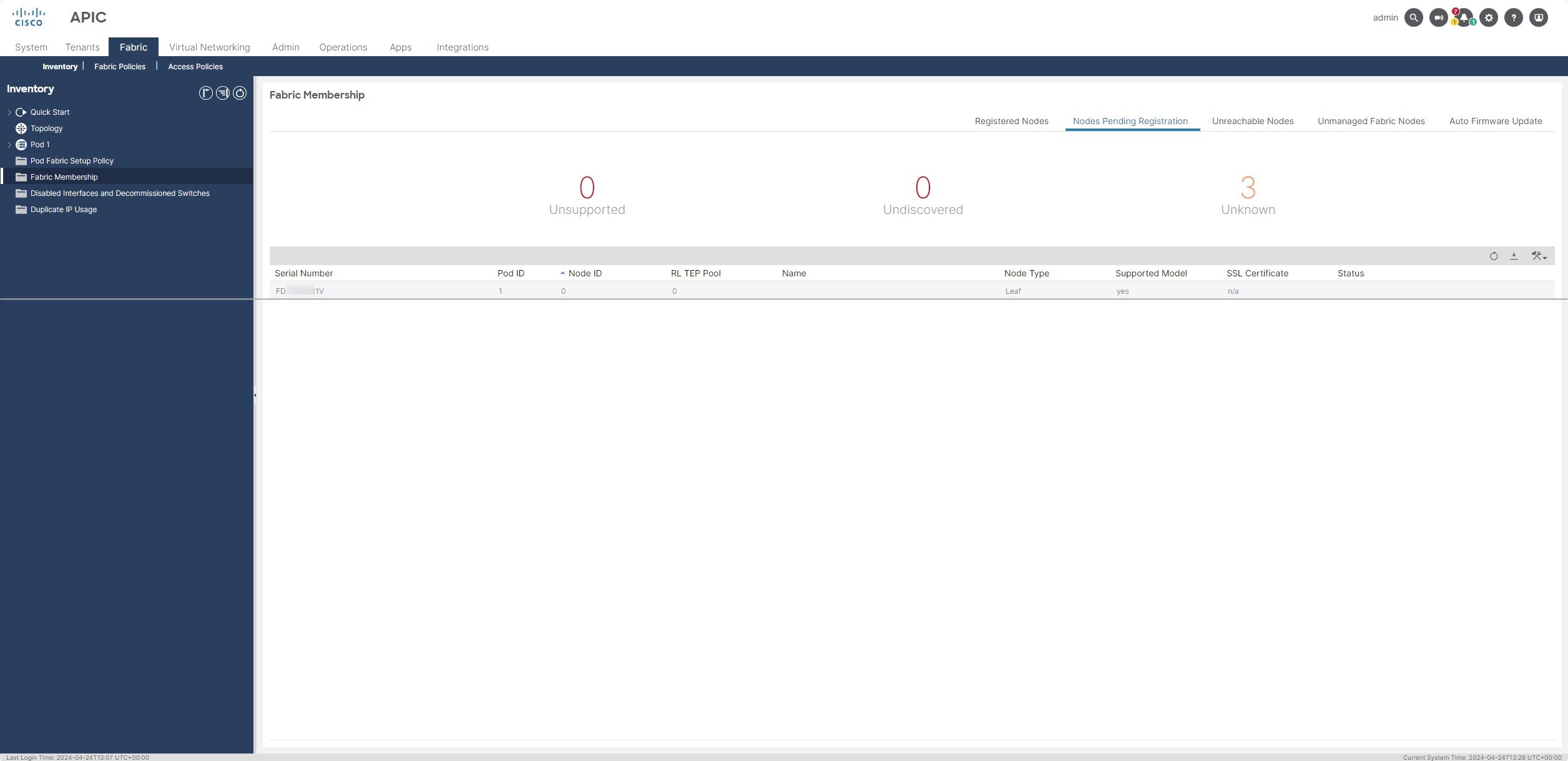
Login to the APIC by using the admin username and the password that to chosen previously. Go to:
Fabric -> Inventory -> Fabric Membership -> Nodes Pending Registration
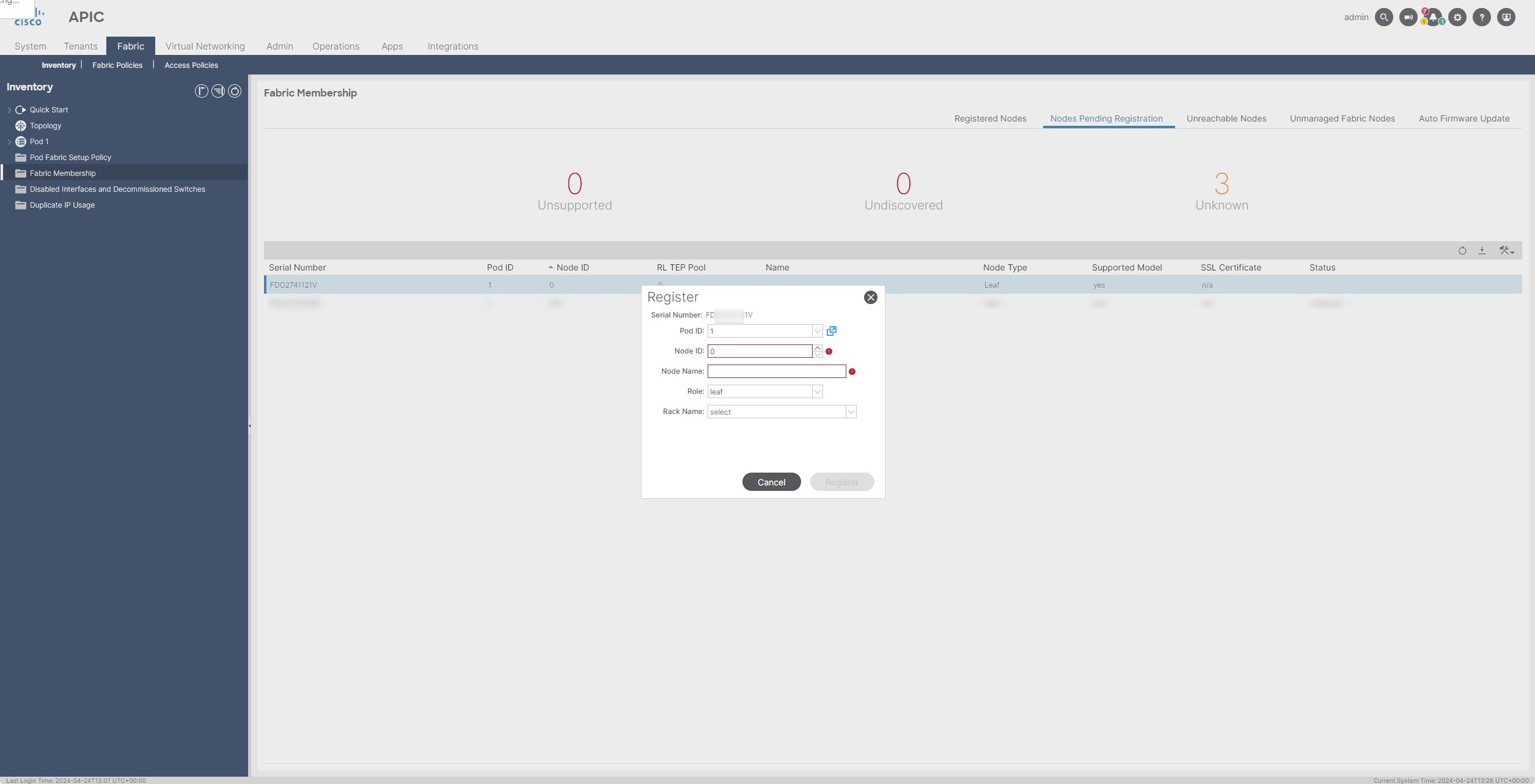
Here you should be able to see the Serial Number of the leaves where the first APIC is attached (fiber interfaces):
Right Click on it and select “Register”
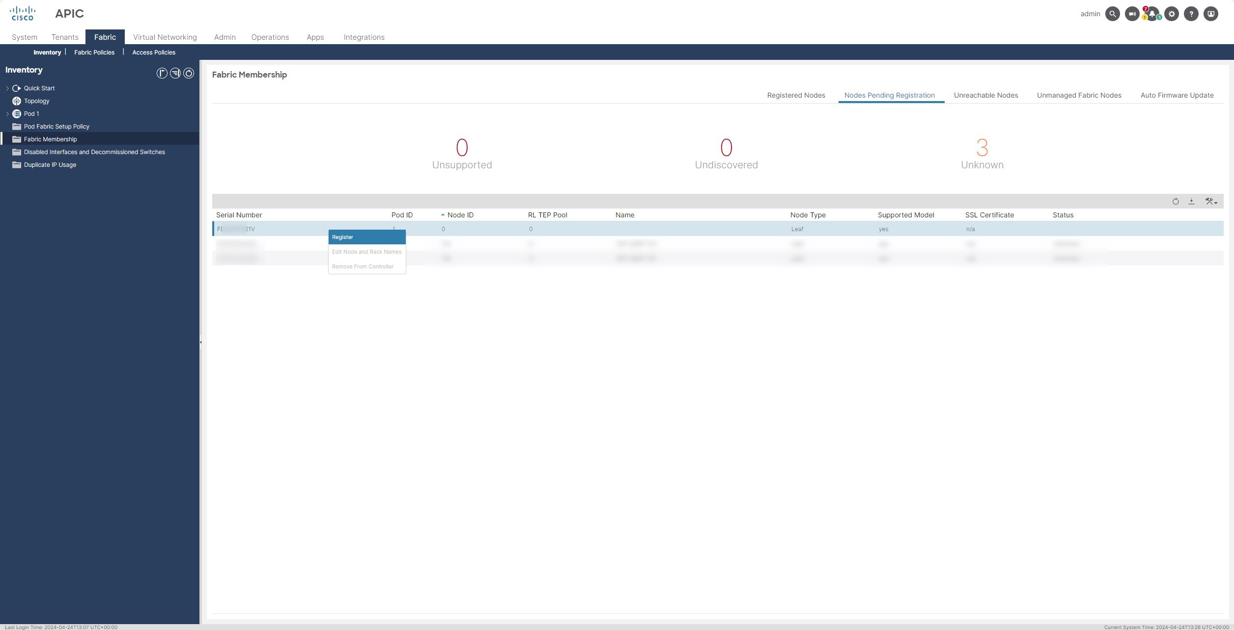
Then, put the Node ID and the hostname of the Leaf. You should have this information in the tables that you’ve filled during the prerequisite tasks
Perfect! Now, when the first leaf has been discovered, in the same section you will see 2 serial number appear, they are the Spine serial numbers!
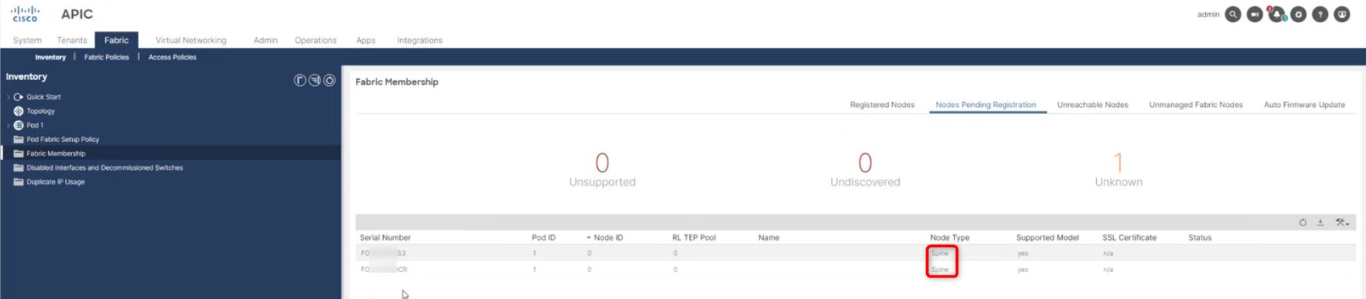
Do the same procedure for them and sequentially also for all the other leaves that will appear in the page.
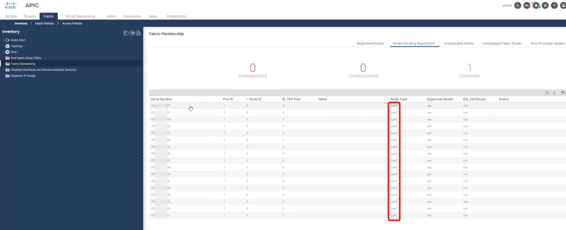
This should be the final view:
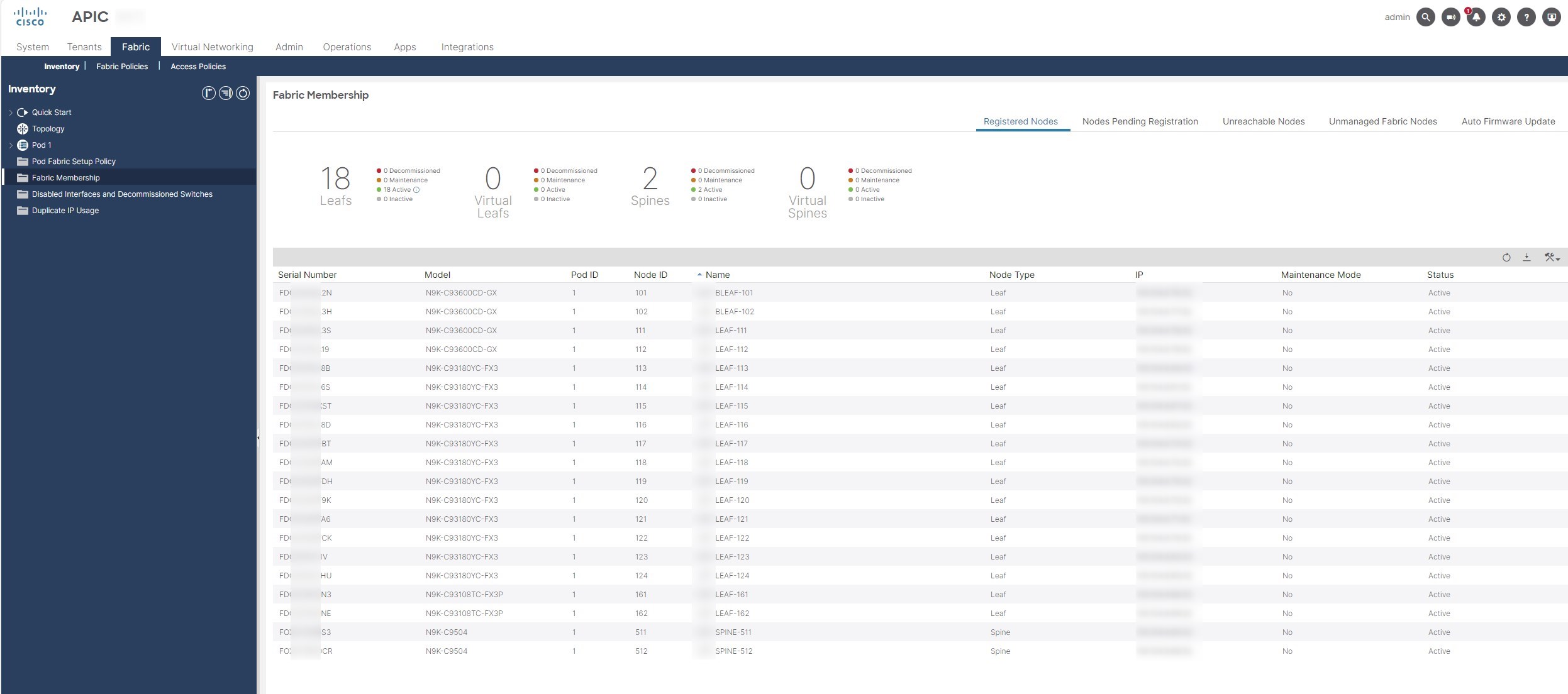
Great, now that all the Spines/Leaves have been discovered, let’s check the APICs status.
From release 5.x to 6.x the APICs discovery process has been changed and with release 6.x nothing has to be done.
What does it mean Riccardo?
It means that you have successfully create your Cisco ACI fabric and now you can proceed with the configuration! 😉
Common Issues
Here are some common issues during the fabric setup:
-
APIC doesn’t discover any leaf
- Make sure that you didn’t enable the LLDP feature from CIMC GUI –> This is very important during the setup of the Fabric. If you enable the LLDP feature before the first discovery, the discovery doesn’t work because the LLDP packets sent by UCS will override the common LLDP packets exchanged between Leaves and APICs (the discovery is based on LLDP)
- Make sure that the leaves/spines are running the ACI firmware version (with “show version” command)
- Make sure that the leaves/spines firmware is in compatibility matrix with the APIC firmware
- Make sure that your are using the “fabric ports” from a leaves/spines prospective
- Try to reset the Leaves/Spines with the following command:
setup-clean-config.sh
reload
-
Issue during the APIC Setup
- Make sure that all the APICs have the same firmware releases
- Check all the physical cabling
- Try to reset the APIC with the following command:
acidiag touch clean
acidiag touch setup
acidiag reboot
Thanks for your time I hope that you’re enjoying my blog!
If you have some questions, please drop me a message through social networks!😊
👈 You can find the relative icons here on the left of the page
Riccardo