Cisco SDWAN: Service Chaining, Firewall Insertion
During this post we’ll implement service chaining, firewall insertion.
Service Chaining
Services such as firewall, load balancer, and intrusion detection and prevention (IDP) are often run within a virtualized environment, and they may physically be centralized in one location or in several locations for redundancy.Services may be internal, cloud based, or external subscriptions. Networks must be able to reroute traffic from any location in the network through such services. Customers want the ability to internally spawn or externally subscribe to new services on demand—for capacity, redundancy, or simply to select best-of-breed technologies. For example, if a firewall site exceeds its capacity, a customer can spawn new firewall service at a new location. Supporting this new firewall would require the configuration of policy-based, weighted load distribution to multiple firewalls.
Following are some of the reasons to reroute a traffic flow through a service or chain of services:
- Traffic flow from a less secure region of a network must pass through a service, such as a firewall, or through a chain of services to ensure that it has not been tampered with.
- For a network that consists of multiple VPNs, each representing a function or an organization, traffic between VPNs must traverse through a service, such as a firewall, or through a chain of services. For example, in a campus, interdepartmental traffic might go through a firewall, while intradepartmental traffic might be routed directly.
- Certain traffic flows must traverse a service, such as a load balancer.
How it works
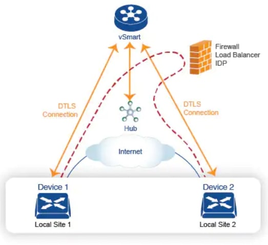
The following figure illustrates how service chaining works in the Cisco SD-WAN solution. The network shown has a centralized vEdge hub router that is connected to two branches, each with a Cisco vEdge device. The standard network design implements a control policy such that all traffic from branch site 1 to branch site 2 travels through the vEdge hub router. Sitting behind the hub router is a firewall device. So now, assume we want all traffic from site 1 to site 2 to first be processed by the firewall. Traffic from the Cisco vEdge device at site 1 still flows to the vEdge hub router, but instead of sending it directly to site 2, the hub router redirects the traffic to the firewall device. When the firewall completes its processing, it returns all cleared traffic to the hub, which then passes it along to the Cisco vEdge device at site 2.
Do you want to know more about Service Chaining? Check this Cisco post!
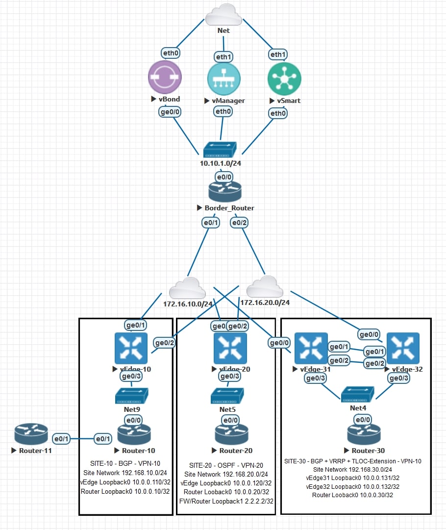
Topology review and requirements
Let’s review together the topology and the requirements for this activity:
AS-IS
The devices that are located in Site-10 are able to talk with all the other devices on the network (both VPN-10 and VPN-20, thanks to route leaking
). This is an important step, keep in mind that we already have a Centralized Policy applied!
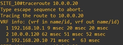
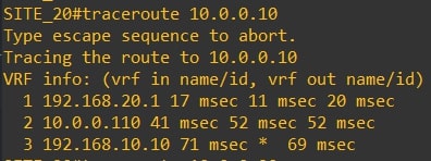
The spoke-to-spoke communication works fine and there is no extra hop in the path.
-
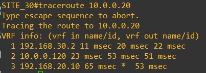
Traceroute from router-10 (10.0.0.10) to router-20 (10.0.0.20) and vice versa
-
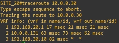
Traceroute from router-10 (10.0.0.10) to router-30 (10.0.0.30) and vice versa
-
Traceroute from router-20 (10.0.0.20) to router-30 (10.0.0.30) and vice versa
Now let’s review the omp route table from vEdges points of view:
-
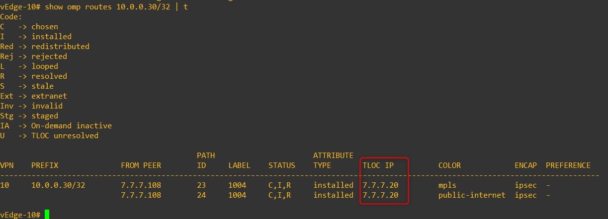
vEdge-10 omp routes to 10.0.0.30/32 (Router-30 looback0)
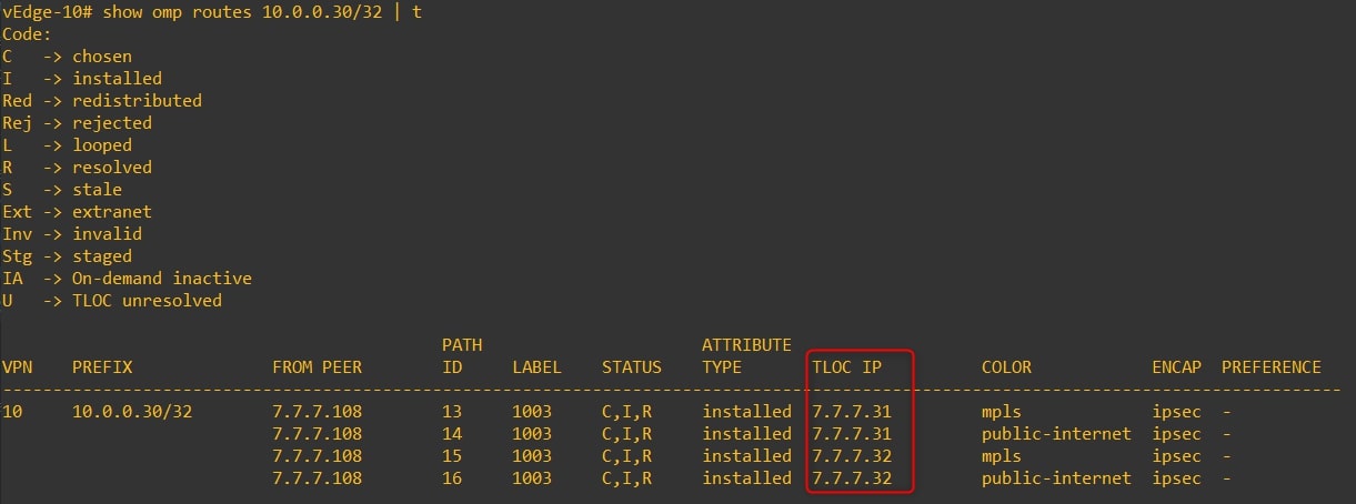
Next TLOC IP is 7.7.7.31 (vEdge-31) and 7.7.7.32 (vEdge-32) -
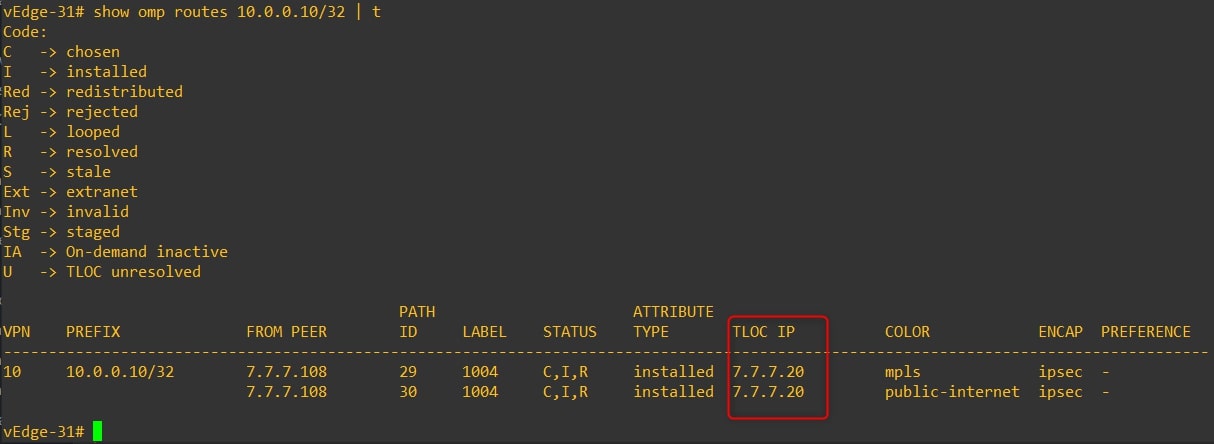
vEdge-31 omp routes to 10.0.0.10/32 (Router-10 looback0)

Next TLOC IP is 7.7.7.10 (vEdge-10) -
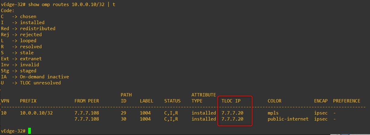
vEdge-32 omp routes to 10.0.0.10/32 (Router-10 looback0)
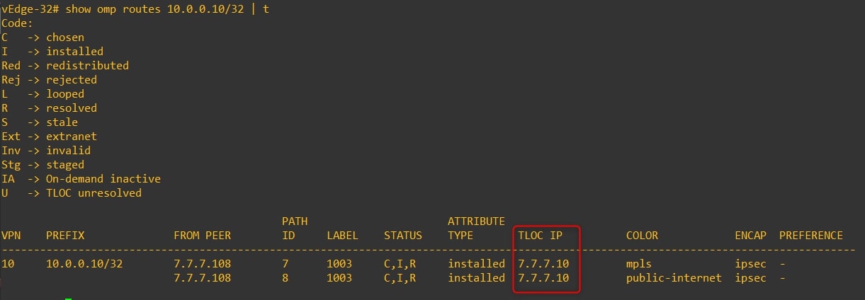
Next TLOC IP is 7.7.7.10 (vEdge-10)
Requirements
The traffic from Site-10 to Site-30 and vice versa must go through the “firewall” located on Site-20. I configured the Loopback1 into Router-20: 2.2.2.2/32 in order to replicate the firewall.
In this lab we’ll consider Site-20 as “Hub”, and sites 10 and 30 as “Spoke”
Disclaimer
I’m using the following release: 20.3.5
If you are not confident about the procedure, test it in your lab environment before applying changes in production.
Configure Service Chaining
First, we need to create the service and propagate it from vEdge-20. I assume that you already have all the VPNs up & running 😉
- Feature Template - VPN 0
Configurations>Template>Feature>Name of your Feature Template related to VPN-20 (in my case it’s TF_VPN-20)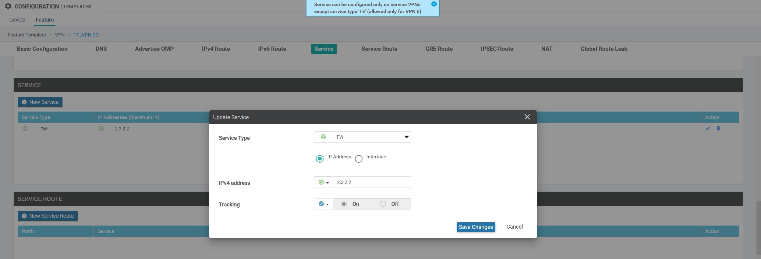
Configure Centralized Policy
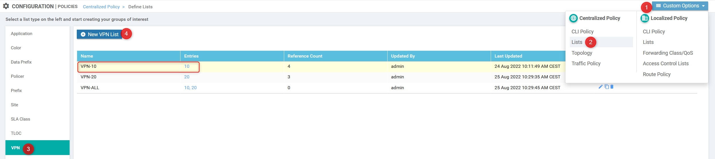
First, click on we need to create Groups of Interest, AKA List.
-
VPN List
Custom Options(centralized policy)>Lists>VPN>New VPN List: Here we need to define the VPN that will use the Service [VPN-10]
-
Site List
Custom Options(centralized policy)>Lists>Site>New Site List: Here we need to define the Sites that will use the Service [Site10 and Site30]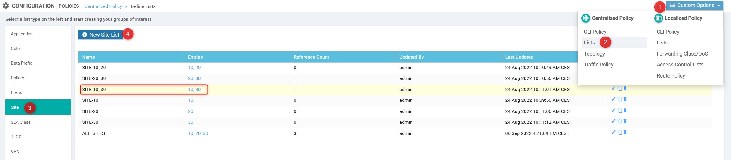
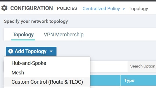
Now, using the Custom Options, create the Custom Control:
- Custom Options(centralized policy)>Topology>Add Topology>Custom Control(Route & TLOC)
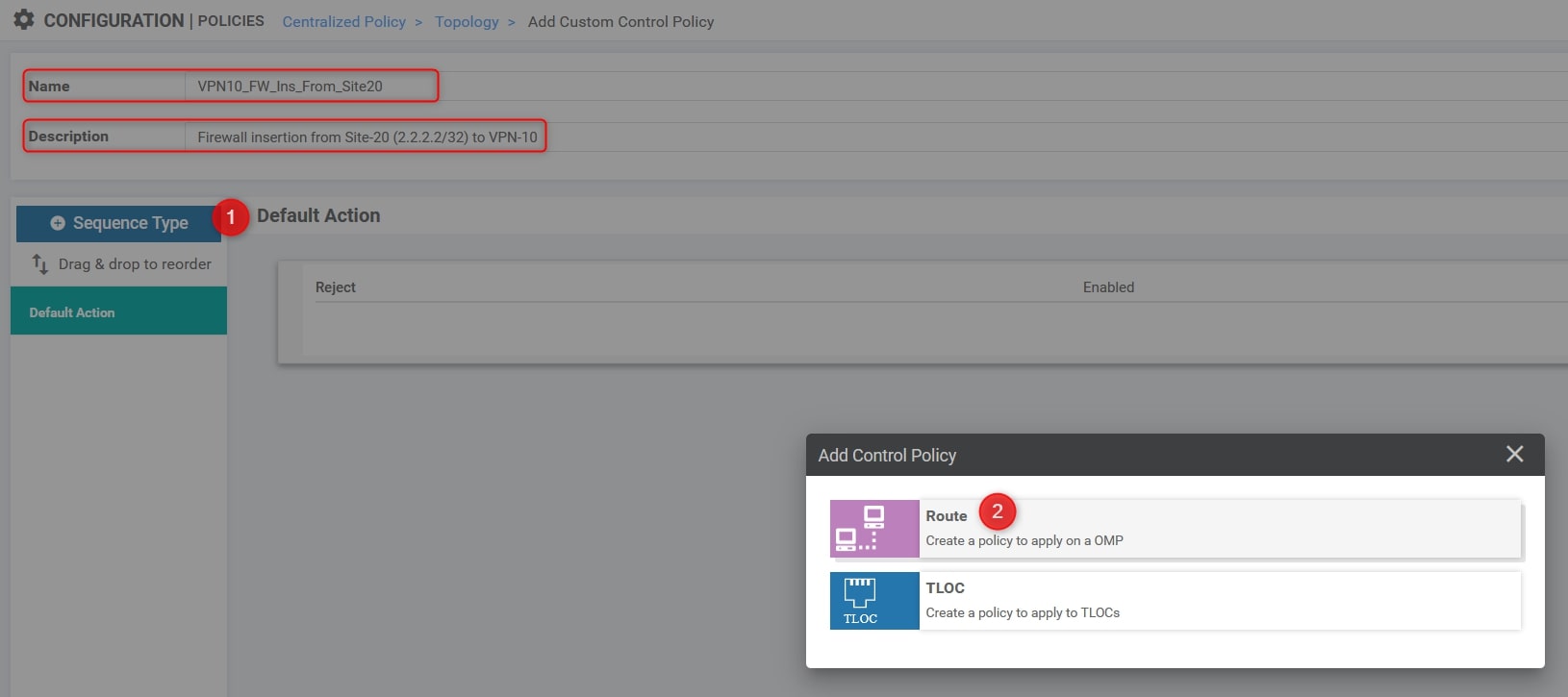
Here we need to specify the following parameters:
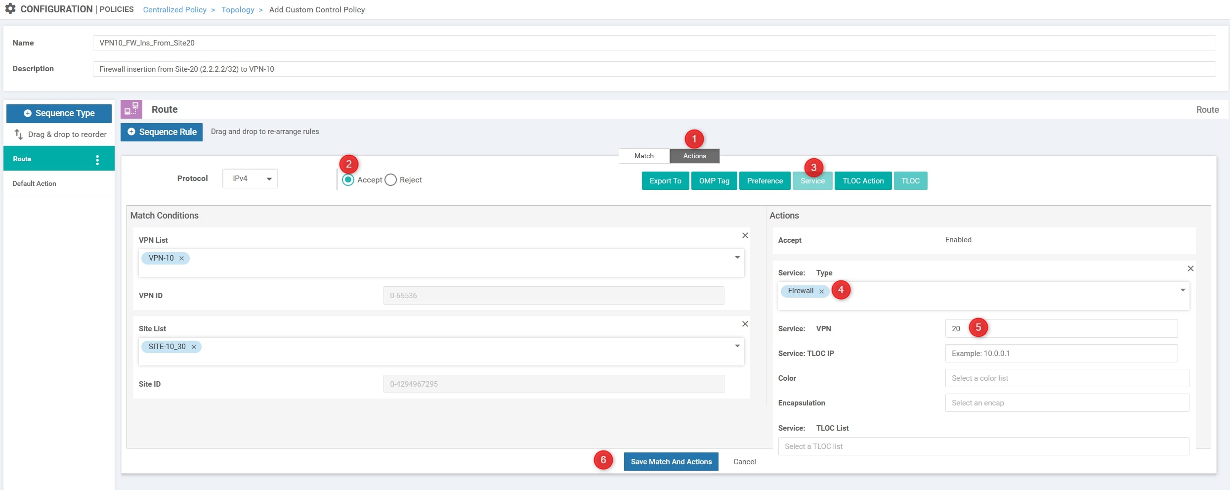
- Name: VPN10_FW_Ins_From_Site20
- Description: Firewall insertion from Site-20 (2.2.2.2/32) to VPN-10
- The Site IDs.
- The VPN ID.
- Change the default action from reject to accept.
Click on “Sequence Type” and choose “Route”
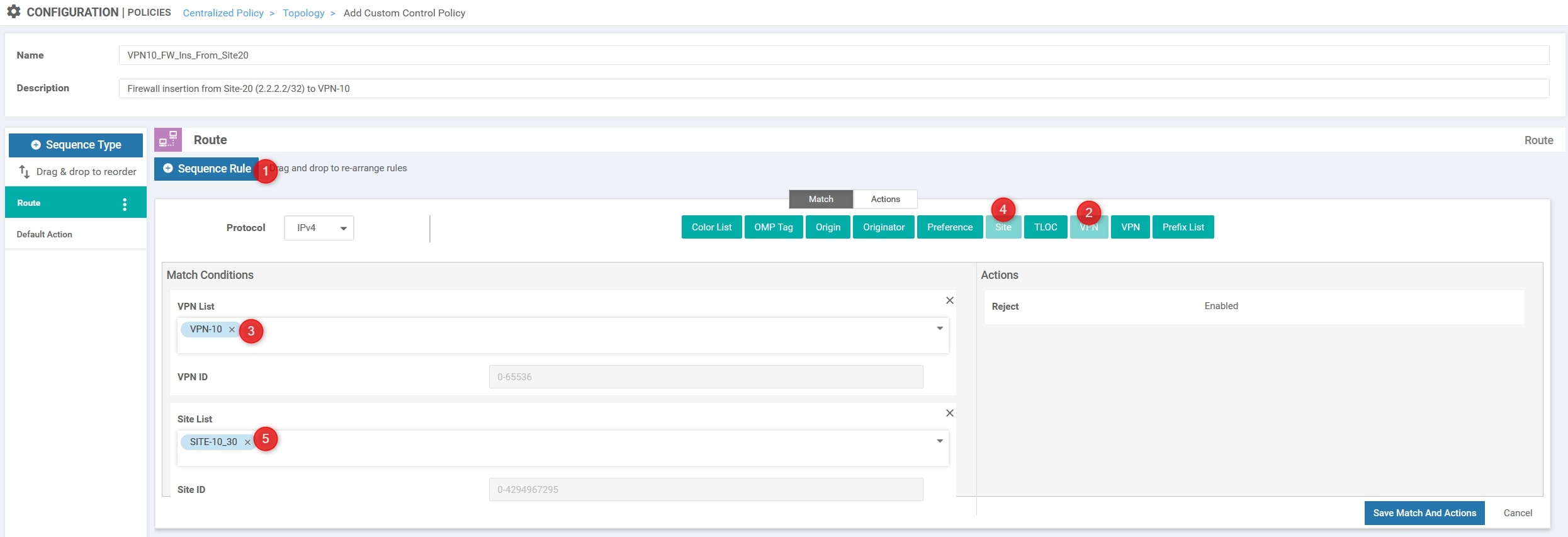
Click on “Sequence Rule” and choose “VPN” (the first one refers to VPN List, the second one refers to VPN ID) and “Site”. In this example we’ll choose “VPN-10” as VPN List and “SITE-10_30” as Site List, here is the configuration:
Then, in the “Action” section change it from “Reject” to “Accept” and choose “Service”. Here we need to select the “Firewall” as Service Type with VPN ID 20 and click “Save Match And Actions”:
The final step is to modify the default action from “Reject” to “Accept”:
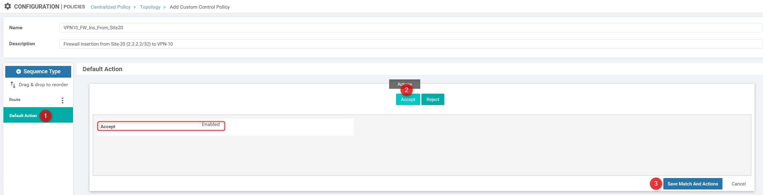
You can now press the “Save Control Policy” at the bottom of the page 😉
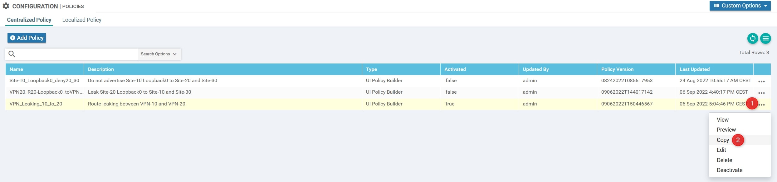
Perfect, now we need to create/compose our policy. In our topology we already have a Centralized Policy applied and it’s fundamental for us because it allows the communication between VPN-10 and VPN-20 (Policy called “VPN_Leaking_10_to_20”).
Copy the policy and create the new one called:
- Policy Name: VPN-Leaking_FW-Insertion
- Description: VPN Leaking between VPN-10 and VPN-20 + FW Insertion from Site-20 VPN-20
Now let’s edit this new policy (VPN-Leaking_FW-Insertion):
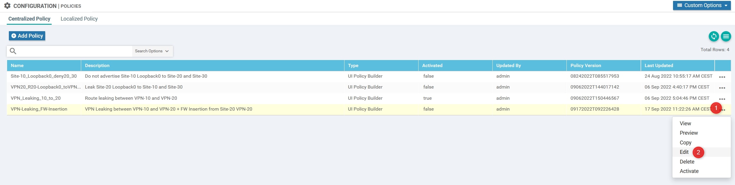
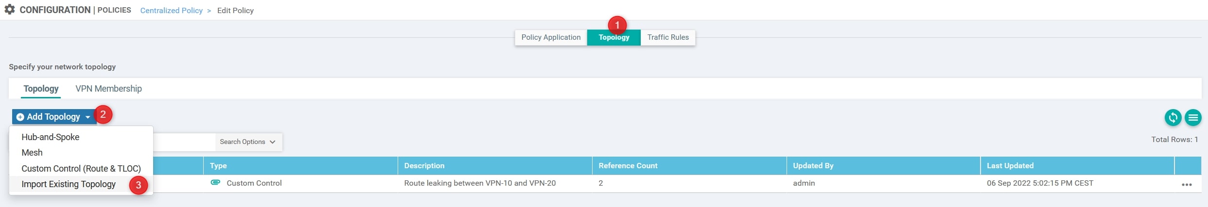
Edit Policy>Topology>Add Topology>Import Existing Topology:
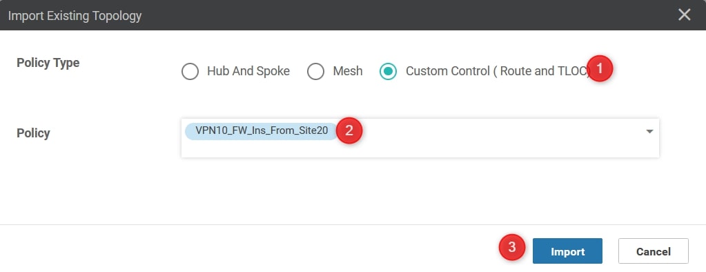
Perfect, now choose “Custom Control (Route and TLOC)” and select the Custom Control policy that we created:
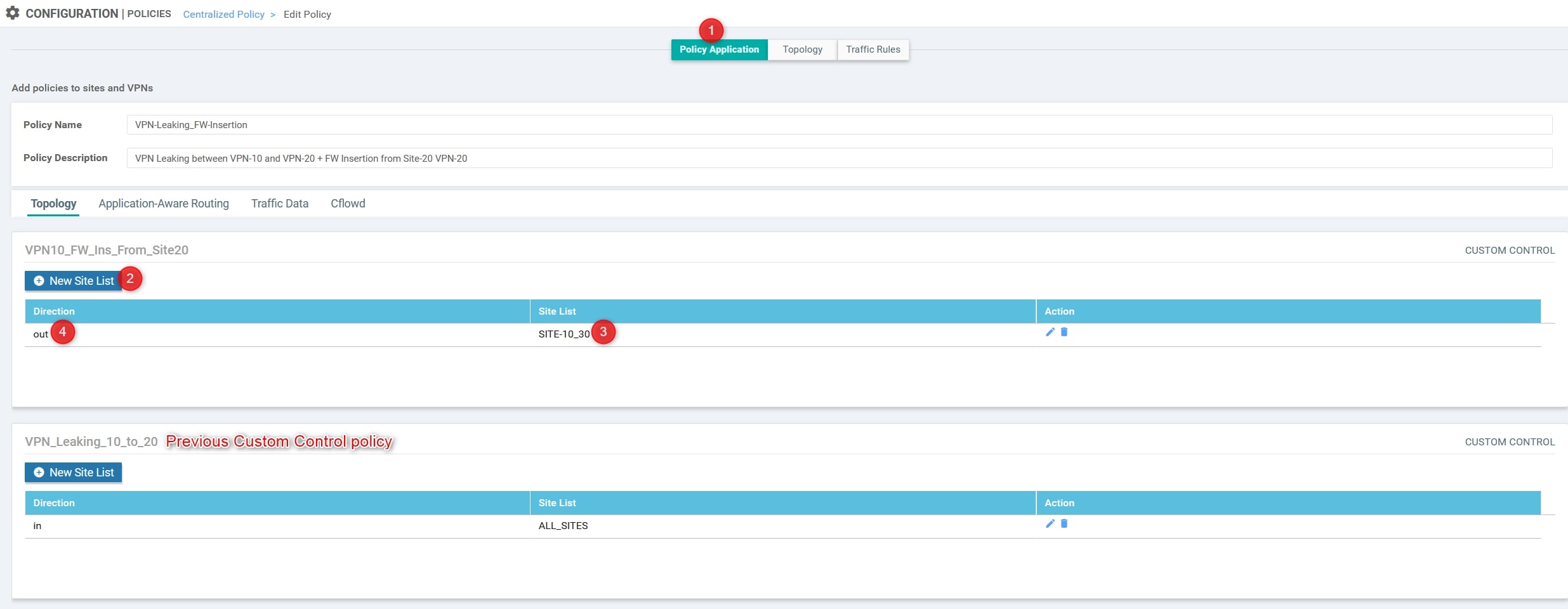
Ok, now go back to “Policy Application” and both the “Site List” and the “Direction”:
You can now press the “Save Policy Changes” at the bottom of the page.
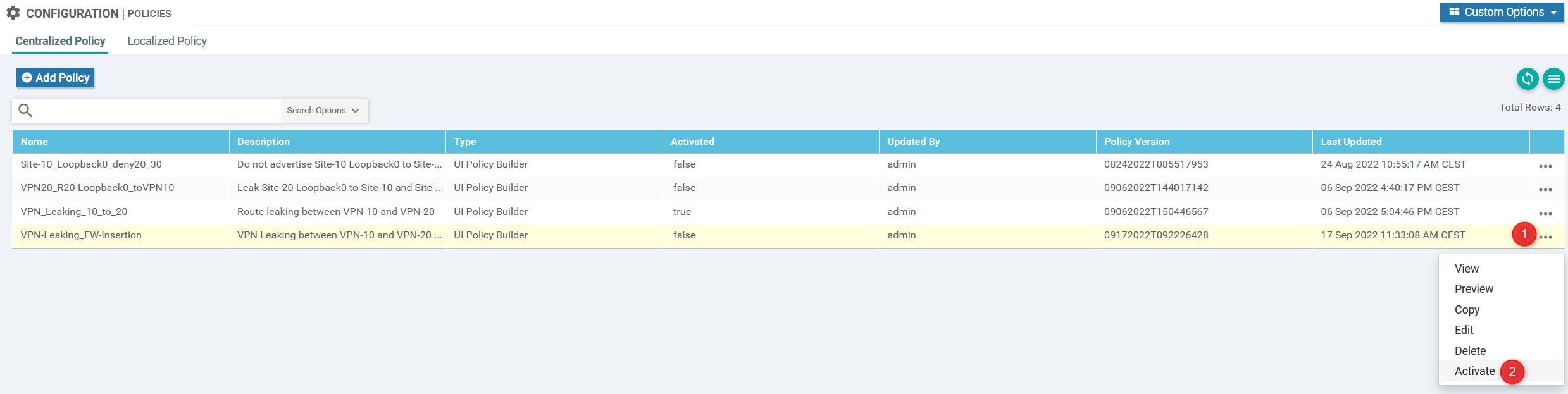
Finally, activate it:
Verify
Now we need to verify that the policy is working properly. Let connect to vEdge-10 and vEdge-31/32 and verify the next-hop for the router’s loopback:
- vEdge-10
As you can see, from vEdge-10 point of view the next hop for this specific subnet is vEdge-20 and not vEdge-31 and vEdge-32
- vEdge-31
As you can see, from vEdge-31 point of view the next hop for this specific subnet is vEdge-20 and not vEdge-10
- vEdge-32
As you can see, from vEdge-32 point of view the next hop for this specific subnet is vEdge-20 and not vEdge-10
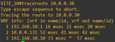
Verify the path using traceroute from Router-10 to Router-30 and vice versa
-
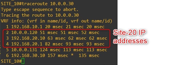
From Router-10 to Router-30
-
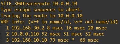
From Router-30 to Router-10
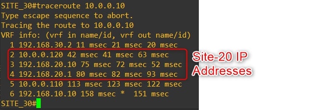
As you can see the traffic goes through Router-20 Loopback1, which simulates our firewall!
Congratulations, you did it!💥
Thanks for your time I hope that you’re enjoying my blog!
If you have some questions, please drop me a message through social networks!😊
👈 You can find the relative icons here on the left of the page
Riccardo