Cisco SDWAN Hub-and-Spoke Topology!
Do you want to configure a Hub-and-Spoke topology? Check it out!! 😊
Cisco SDWAN default behaviour
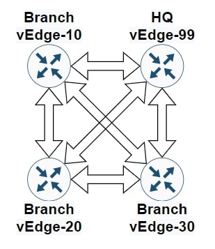
In a Cisco SDWAN network, vEdge routers build a full-mesh topology with vEdge routers in other sites. This is the default behaviour, and it means that all devices within a service VPN can communicate with each other. However, a full mesh topology is not always required, and with many vEdge routers, it can even become a scalability issue.
We can implement a Hub-and-Spoke topology in several ways, here are three different options:
- Hub-and-Spoke Topology Policy
- Custom Control Topology Policy
- Centralized CLI Policy [not in this article]
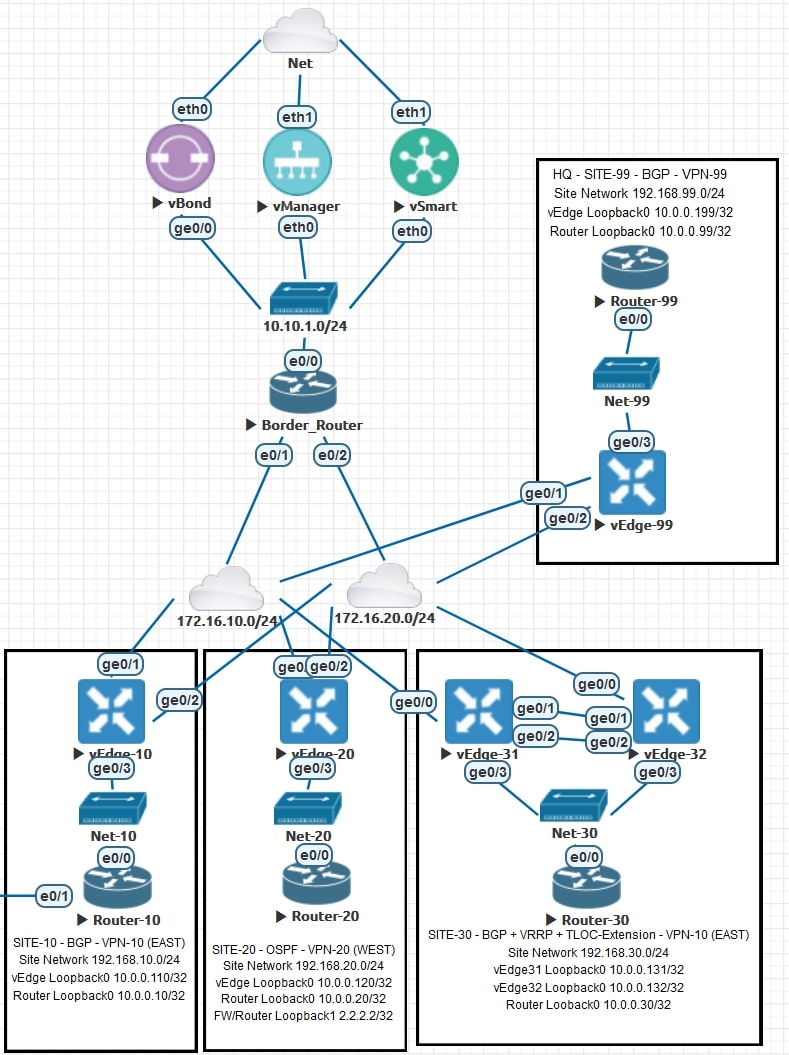
Topology review and requirements
Let’s review together the topology and the requirements for this activity:
AS-IS
Site-99 represents our HQ.
Sites 10, 20 and 30 are branches.
The route leaking between all the VPNs is already implemented. For more information about Route Leaking, please check this post
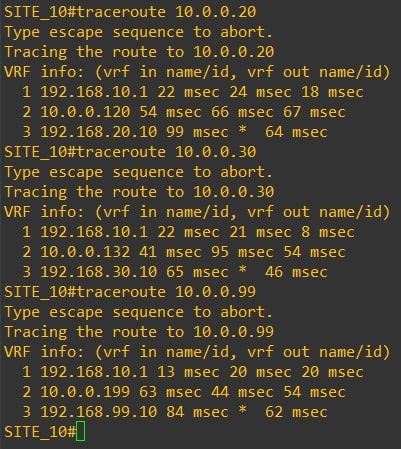
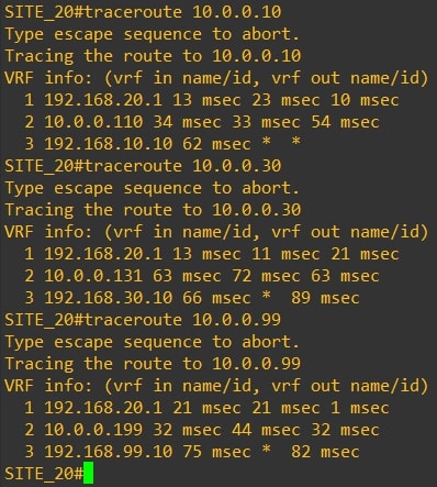
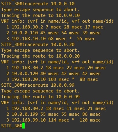
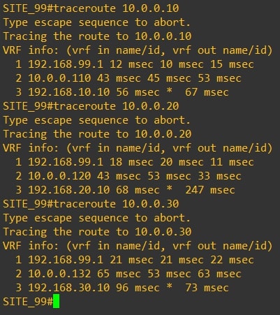
The communication between all the routers is direct, with no extra hops in the middle. Here are the actual traceroutes:
-
Router-10
-
Router-20
-
Router-30
-
Router-99
Requirements
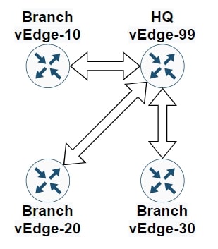
The CIO of the company asked us to change this behaviour and implement a Hub-and-Spoke topology, all the traffic must pass through the HQ (Site-99).
TO-BE
The communication between all the routers must pass through vEdge-99
Disclaimer
I’m using the following release: 20.3.5
If you are not confident about the procedure, test it in your lab environment before applying changes in production.
RFC-1918 OMP Injection
The first thing to do is to inject the RFC-1918 subnets into OMP from the HQ. Why? Because with the following steps we’ll send only the HQ subnets to all the branches, so the branches need a route to reach other branches. Great! Let’s begin.
Note: For this topology should be enough the 10.0.0.0/8 subnet, but for exercise, we’ll announce all the RFC-1918 subnets
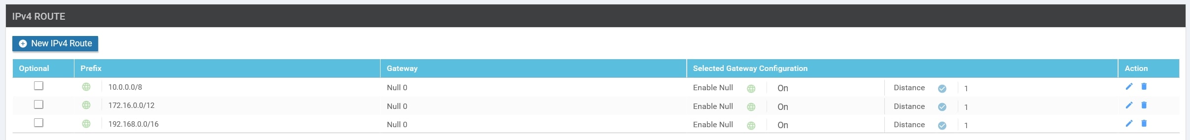
- 10.0.0.0/8
- 172.16.0.0/12
- 192.168.0.0/16
Perfect, in order to announce a subnet that is not in our routing table, we need to create a “fake” static route, pointing to Null0, and advertise it into OMP.
You need to go into the HQ Service VPN Feature Template and apply the following configurations:
-
Static routes pointing to Null0:
-
Advertise OMP Networks:
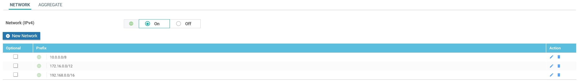
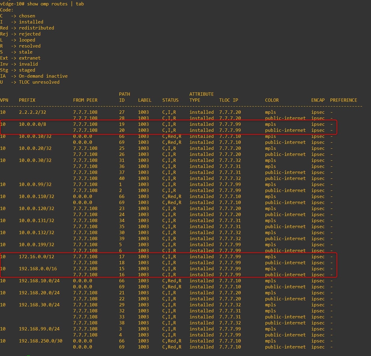
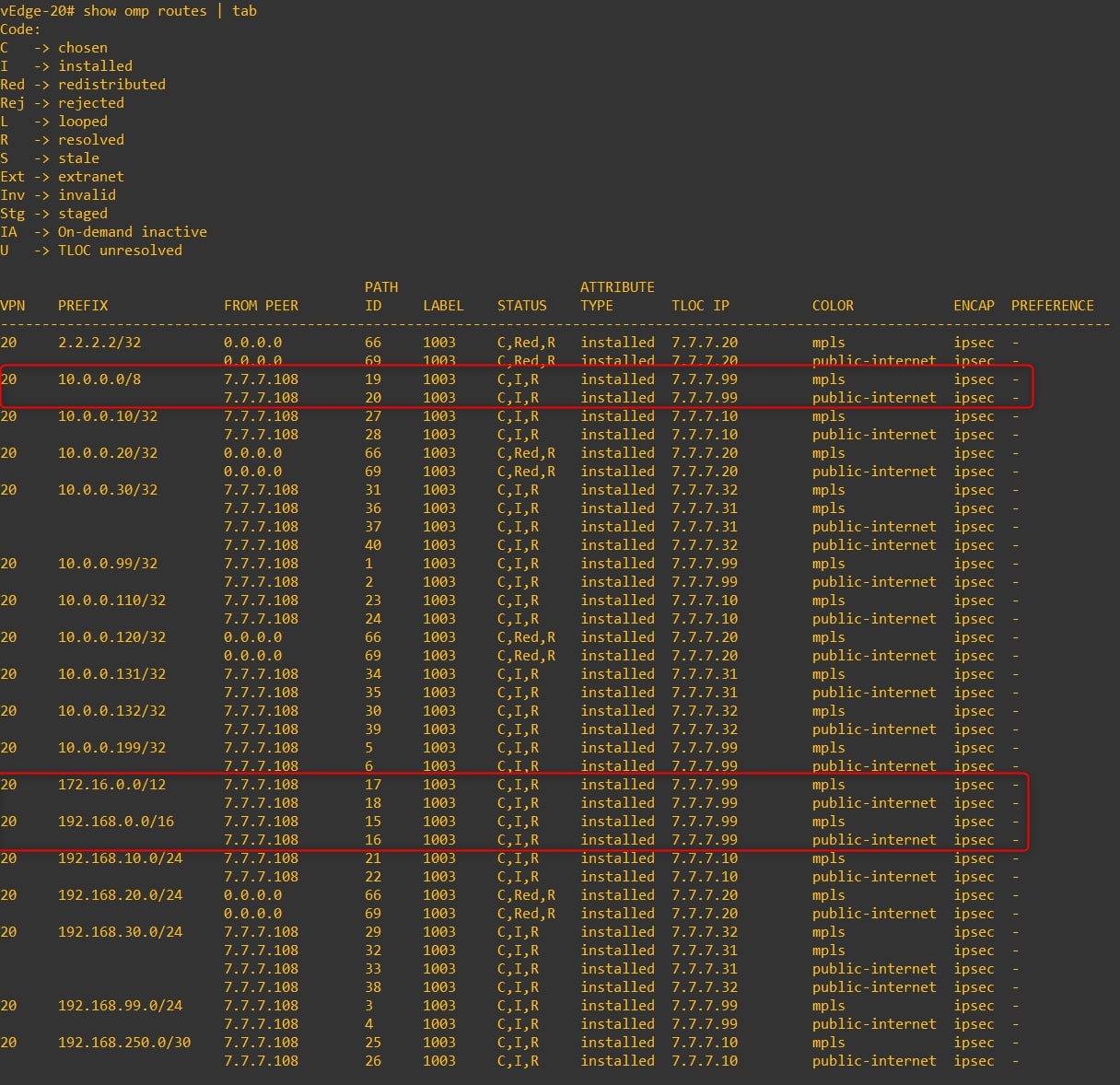
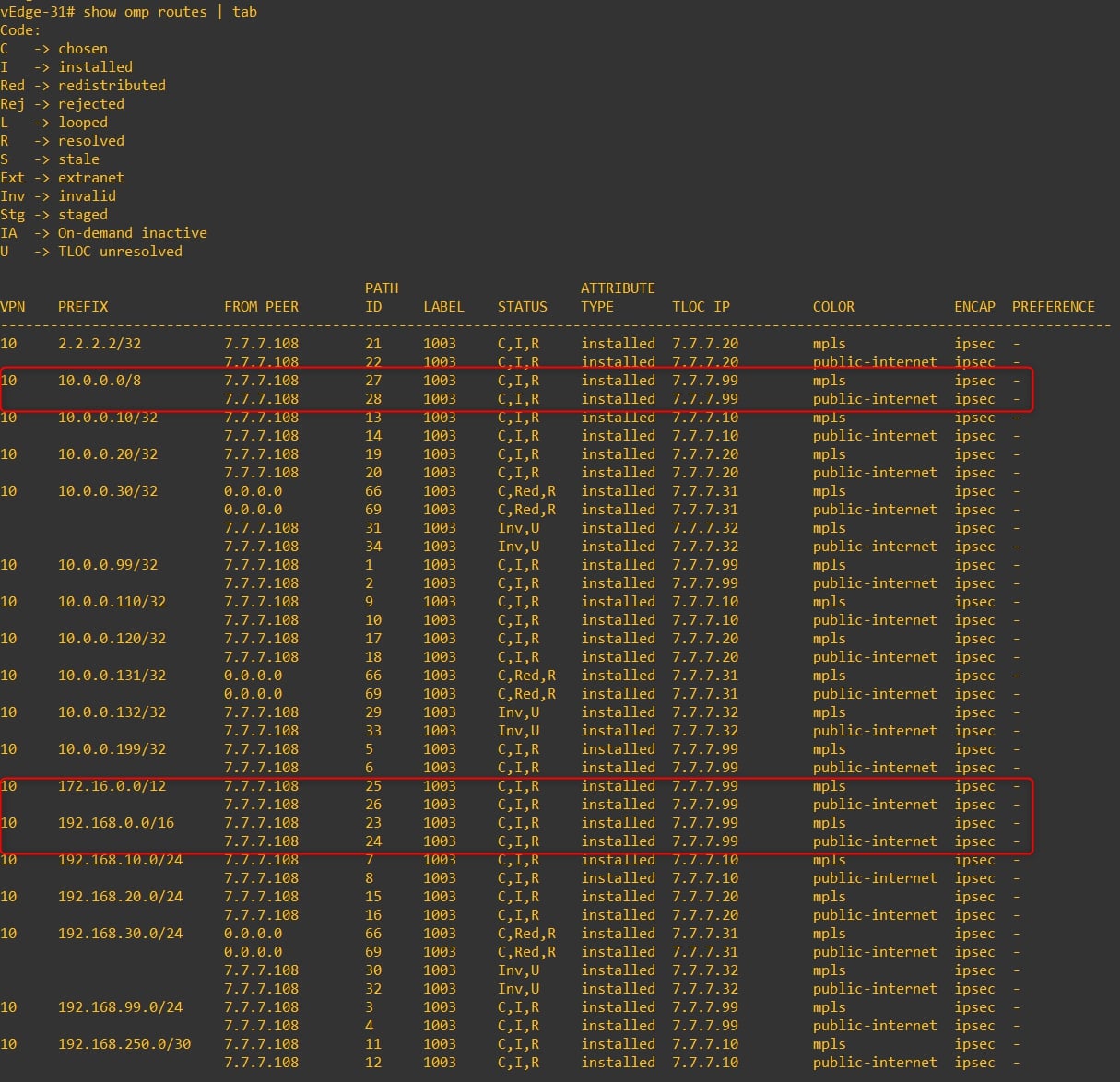
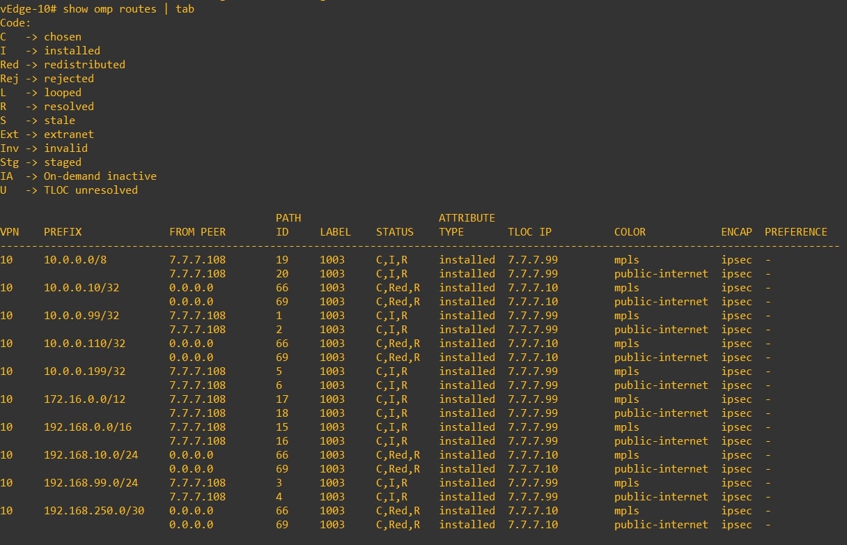
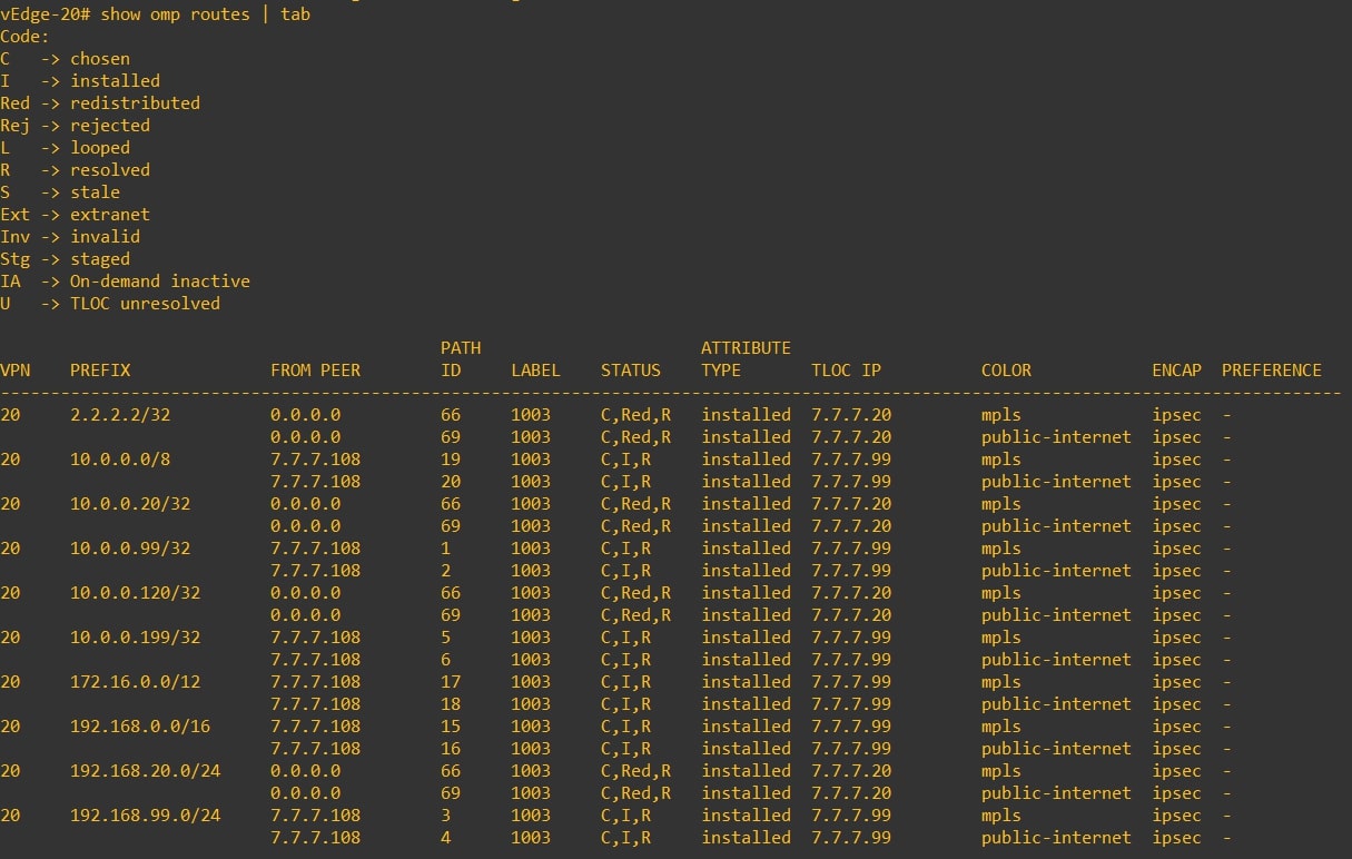
Great, now verify if the remote vEdges are receiving the RFC-1918 subnets via OMP from HQ vEdge-99:
-
vEdge-10
-
vEdge-20
-
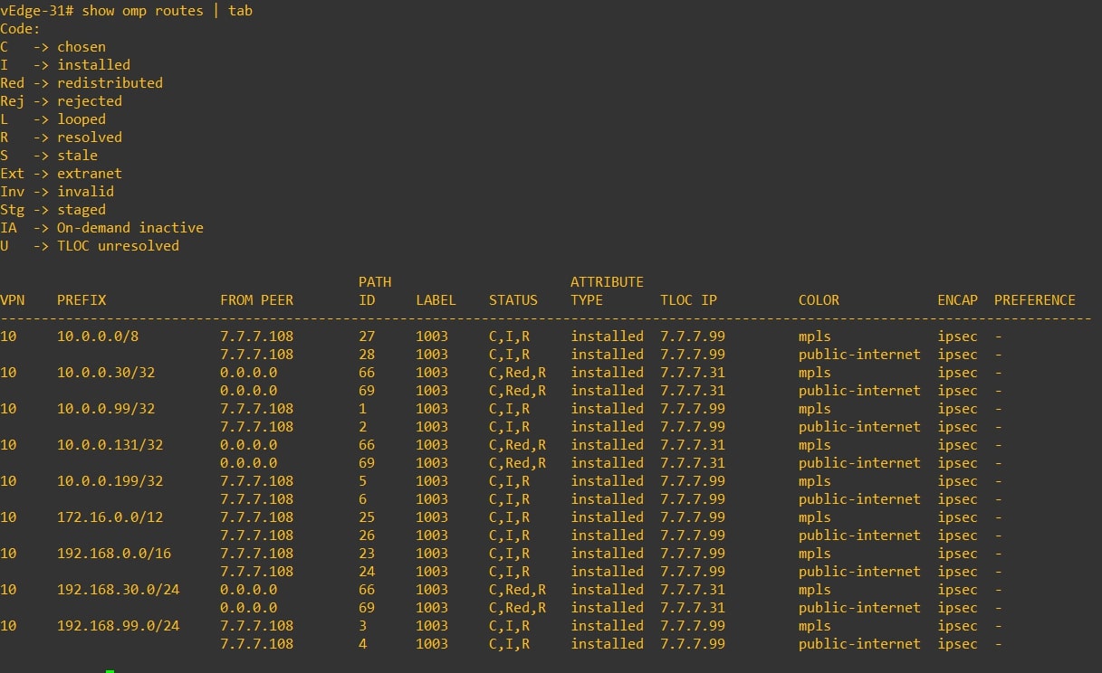
vEdge-31
-
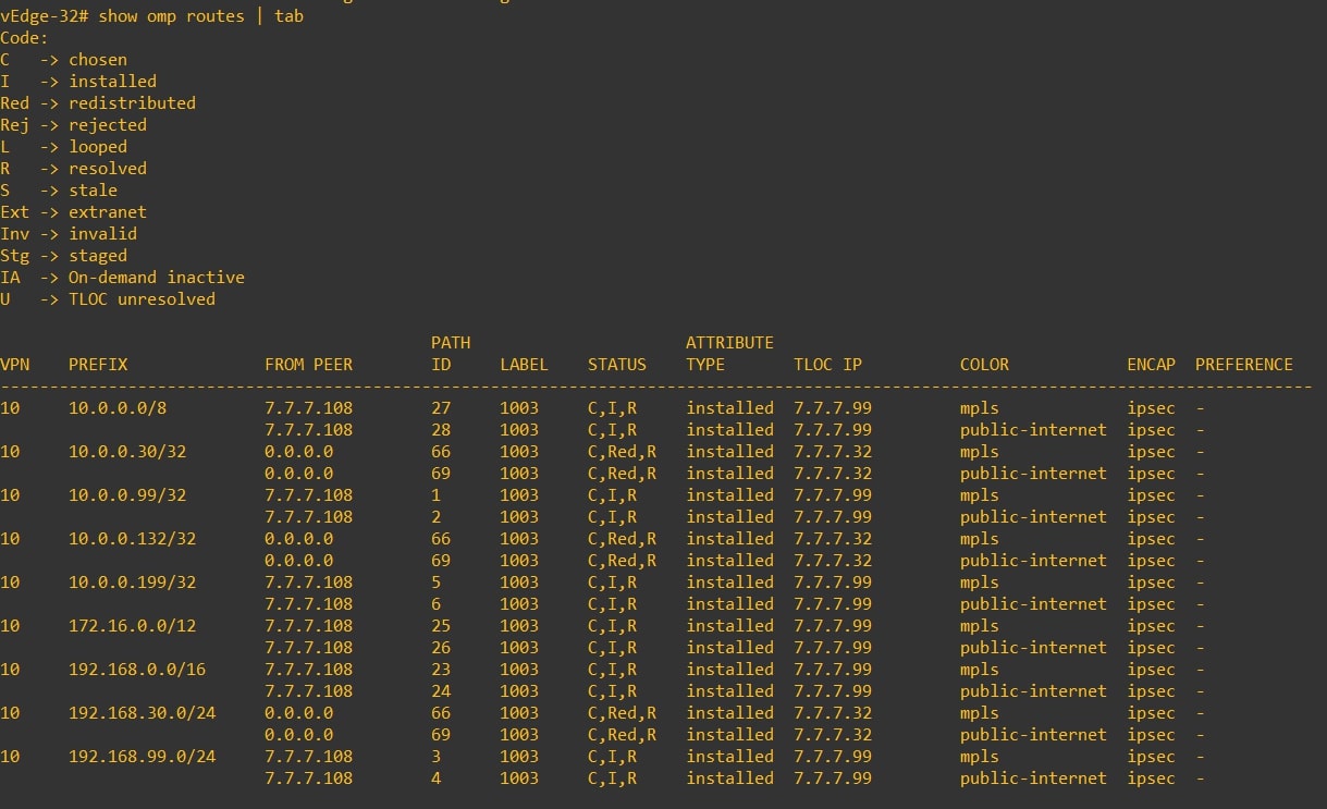
vEdge-32
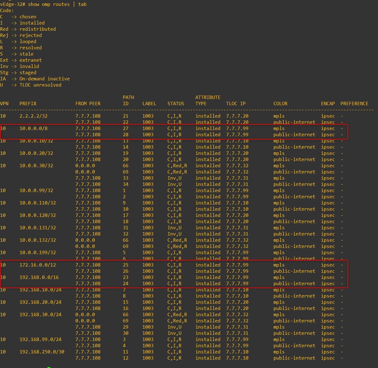
Perfect, now we can proceed with the policy configuration! 😊
Lists
During this procedure we’ll use some lists, let’s configure them:
-
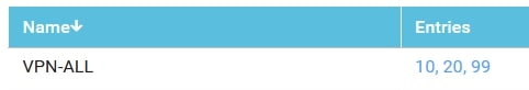
VPN Lists (Please, use your own values)
- Name: VPN-ALL
- Value: 10,20,99
-
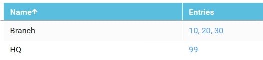
Site Lists (Please, use your own values)
-
Name: Branch
-
Value: 10,20,30
-
Name: HQ
-
Value: 99
-
-
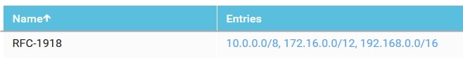
Prefix Lists (Please, use your own values)
- Name: RFC-1918
- Value: 10.0.0.0/8,172.16.0.0/12,192.168.0.0/16
Configuration 1 - Hub-and-Spoke Topology Policy
Ok, let’s start configuring the Topology Policy.
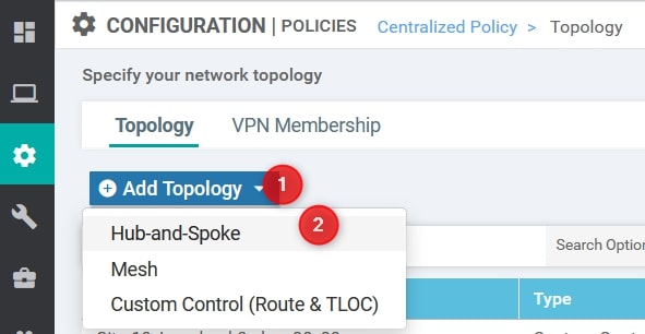
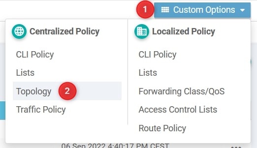
From Configuration -> Policies go to Custom Options and select Topology

From here, select Add Topology and then Hub-and-Spoke
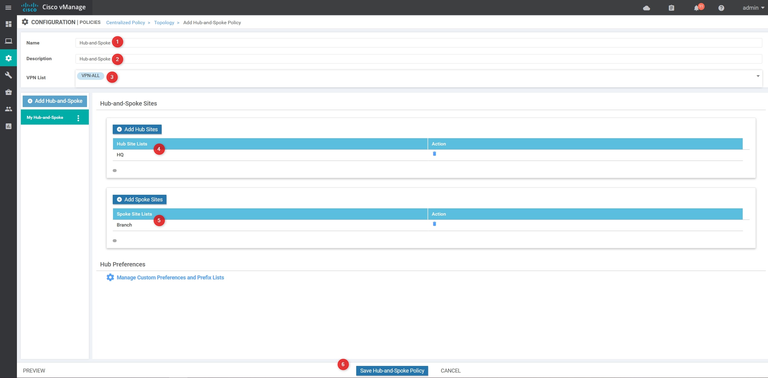
Now, we need to provide the following values (Please, use your own values):
- Name: Hub-and-Spoke
- Description: Hub-and-Spoke
- VPN List: VPN-ALL –> This list contains all the VPNs
- Hub Site List: HQ
- Branch Site List: Branch
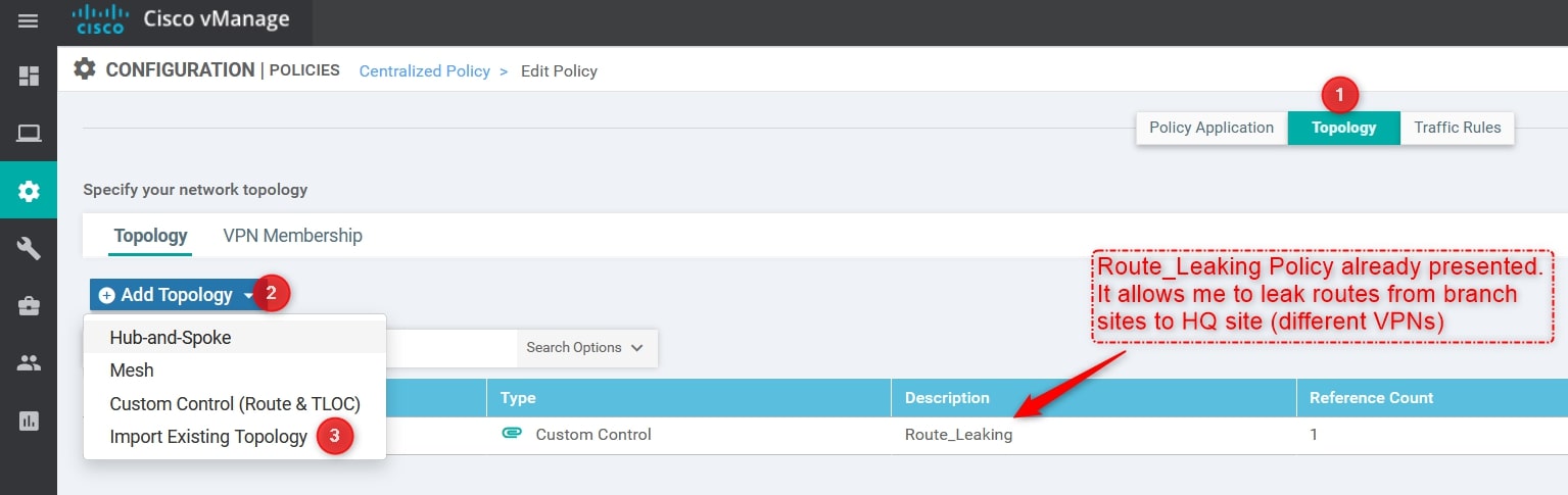
Perfect, now we can apply the Topology Policy to our Centralized Policy! Remember that we can have only one centralized policy applied, so we need to edit the active one and import the Topology Policy created.
From Configuration -> Policies selects your active policy and click Edit. Then, import the Hub-and-Spoke Policy created:
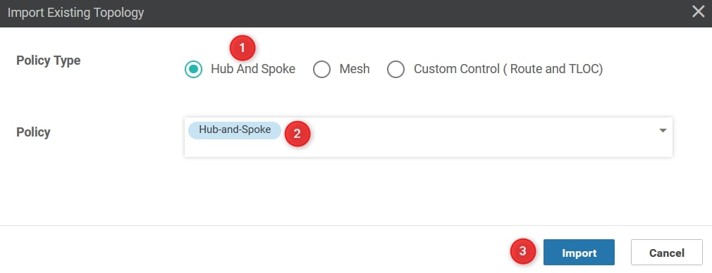
From the Import Existing Topology click Hub And Spoke and select the Policy created in the previous step and then click import:
Great! Save the policy changes, activate the policy and wait a couple of seconds 😊
Verify
Perfect, let’s see the output.
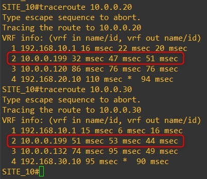
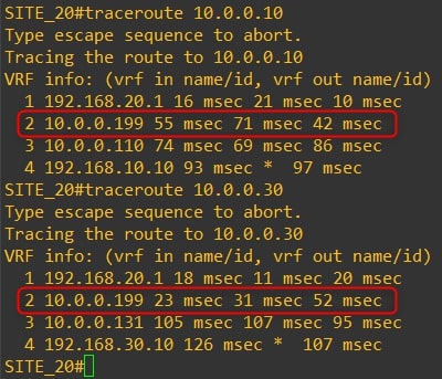
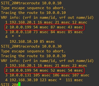
The communication between all the routers now goes through the HQ vEdge-99. Here are the traceroutes:
-
Router-10
-
Router-20
-
Router-30
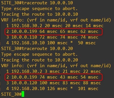
As you can see, the traffic goes through the HQ vEdge-99 and not directly to the remote branch.
If you go to the “RFC-1918 OMP Injection” section, you can see that the routing tables of the vEdges contain all the remote site prefixes. And now? Let see:
-
vEdge-10
-
vEdge-20
-
vEdge-31
-
vEdge-32
Another interesting check could be to verify the bfd sessions, as you can see in the following screenshots the vEdge establish a bfd session only with HQ vEdge:
PRE:
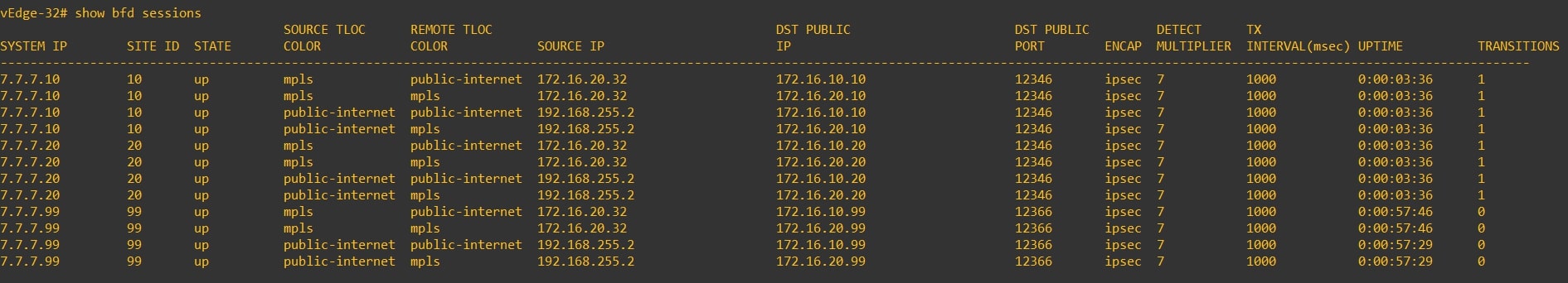
POST:

Congrats! You successfully implemented the Hub and Spoke topology! 💥
Configuration 2 - Custom Control Topology Policy
Another way to configure Hub and Spoke topology could be by using a custom control topology policy.
From Configuration -> Policies go to Custom Options and select Topology
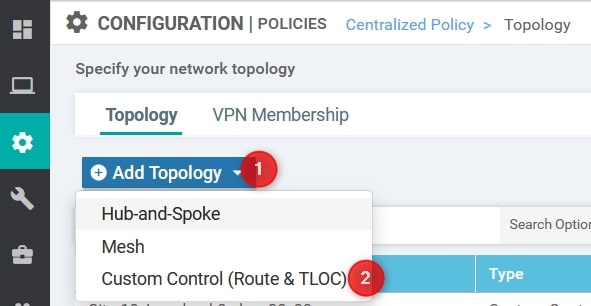
From here, select Add Topology and then Custom Control (Route & TLOC)
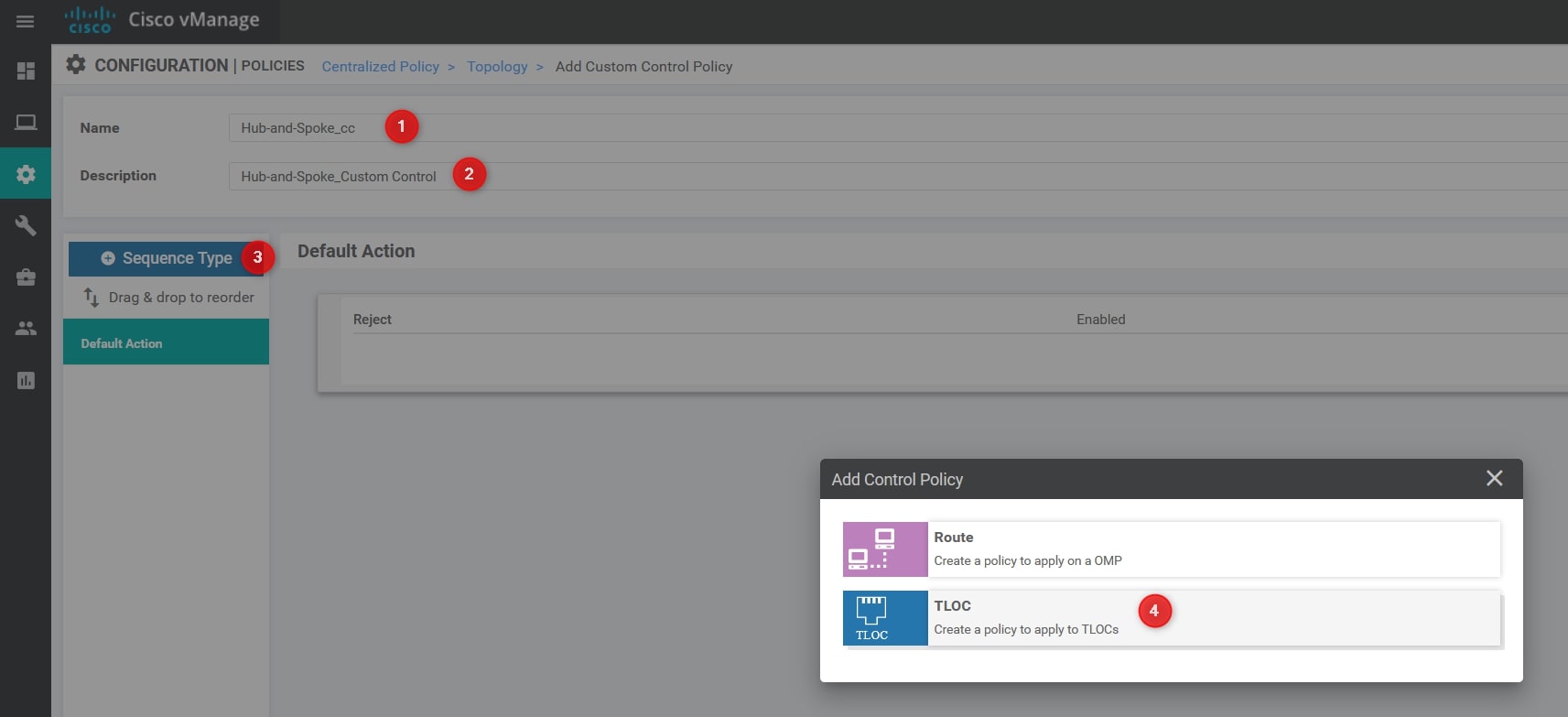
Now, we need to provide the following values (Please, use your own values):
- Name: Hub-and-Spoke_cc
- Description: Hub-and-Spoke_Custom Control
Select Sequence Type and then TLOC.
Now, Click Sequence Rule and, in the Match section select Site and use the HQ Site List defined in the previous step:
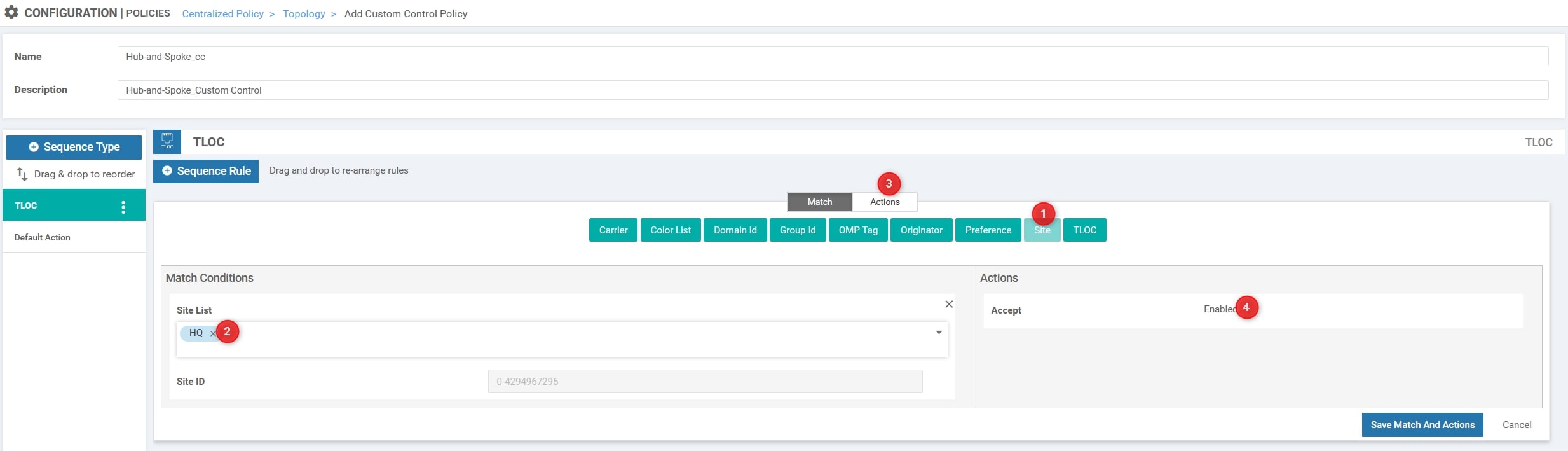
Change the Action to Accept
The last step is to add another Sequence Type and select Route. Then, add the Sequence Rule, select Prefix List and add the RFC-1918 list. Moreover, you must change the Action from reject to Accept.
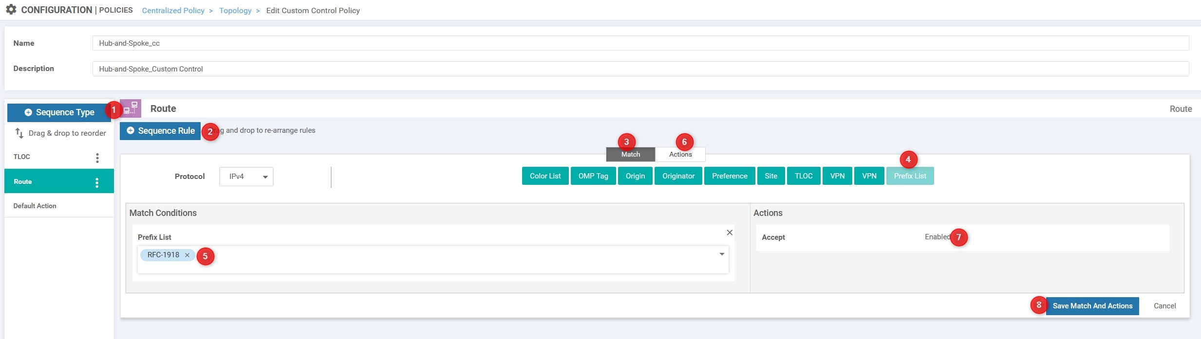
Perfect, leave the Default Action to Reject and click Save Control Policy
Now, we’ll apply this policy outbound to all the branches, so we are telling the vSmart to announce only the HQ TLOC to the branches and deny all the others (default action reject).
Okay, now we can apply the Topology Policy to our Centralized Policy! Remember that we can have only one centralized policy applied, so we need to edit the active one and import the Topology Policy created.
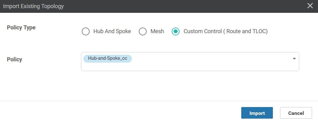
From Configuration -> Policies selects your active policy and click Edit. Then, import the Custom Control Policy created:

From the Import Existing Topology click Custom Control (Route & TLOC) and select the Policy created in the previous step and then click import:
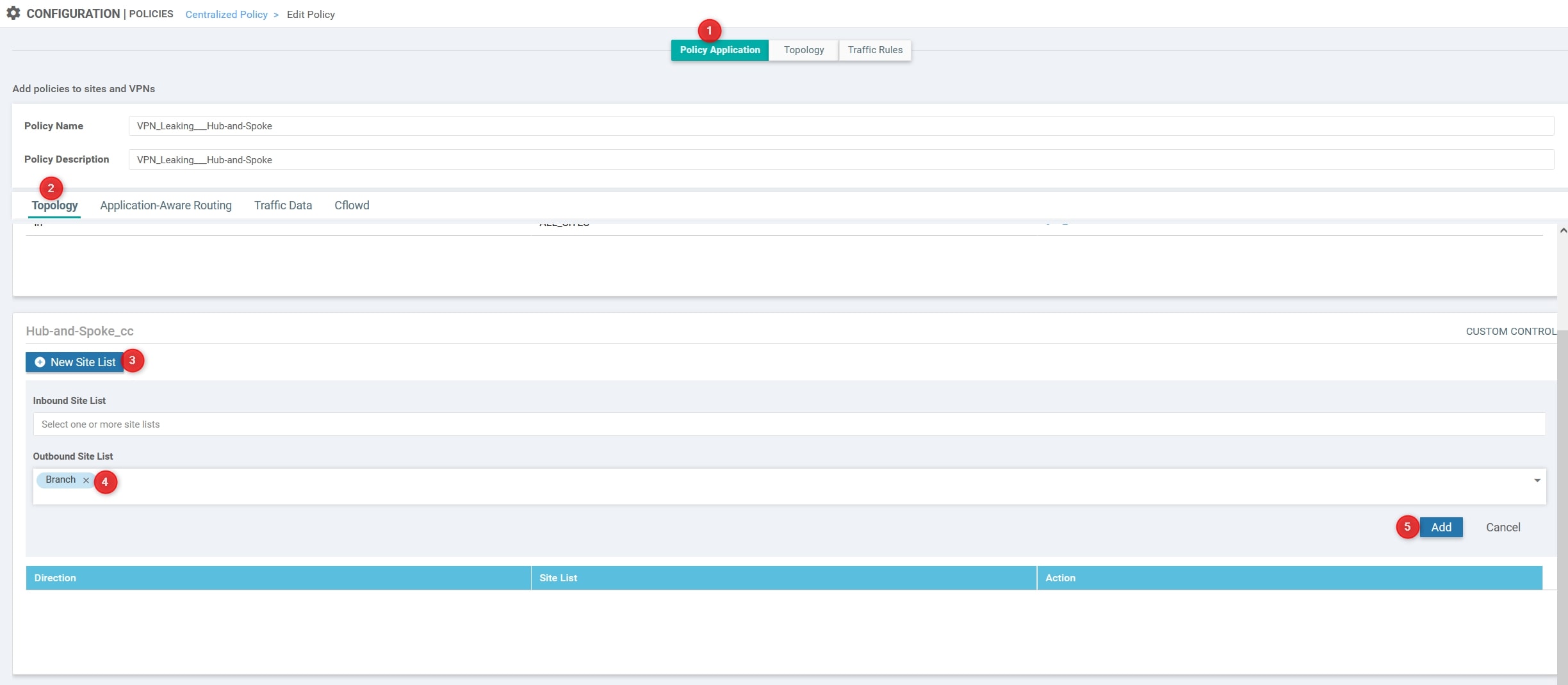
We’re almost done! Move to Policy Application and, under the Hub-and-Spoke_cc section click New Site List. Then, in the Outbound Site List use the Branch list created at the beginning of this procedure. Then, click Add and Save Policy Changes
Verify
Perfect, let’s see the output.
The communication between all the routers now goes through the HQ vEdge-99. Here are the traceroutes:
-
Router-10
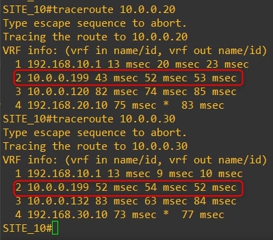
-
Router-20
-
Router-30

As you can see, the traffic goes through the HQ vEdge-99 and not directly to the remote branch.
Congrats! You successfully implemented the Hub and Spoke topology! 💥
Thanks for your time I hope that you’re enjoying my blog!
If you have some questions, please drop me a message through social networks!😊
👈 You can find the relative icons here on the left of the page
Riccardo