How to Build a Cisco SDWAN Lab From Scratch
In this blog I’ll share with you all the necessary information in order to setup and configure your own Cisco SDWAN lab infrastructure using EVE-NG . I’ll post the initial and basic configuration for Controllers, vEdges and branch core switches.
If you don’t have any clue what Cisco SDWAN is, I really recommend you to read this blog post where I introduce this technology and explain several concepts 😊
Ready to create your own lab? LET’S GO!
Prerequisites
- You MUST have a valid Cisco Account in order to download Cisco SDWAN images
- You MUST have a valid Cisco Account in order to create a new smart account (for vEdges onboarding purposes)
For this reason this guide will start with the following steps that are not mandatory at the beginning but without them you can not build your Cisco SDWAN lab Infrastructure
Download Cisco SDWAN images
Here you can find and download the files:
Please consider that in this guide I will use vEdges Cloud. Cisco announces the End-of-Life and End-of-Sale
dates for the Cisco vEdge Cloud and the last software release for vEdge Cloud would be 20.9.x.
The new SDWAN edges will be Catalyst 8000V (here the datasheet
). (maybe I will do a new guide when I will test them)
Creating the SerialFile.viptela file
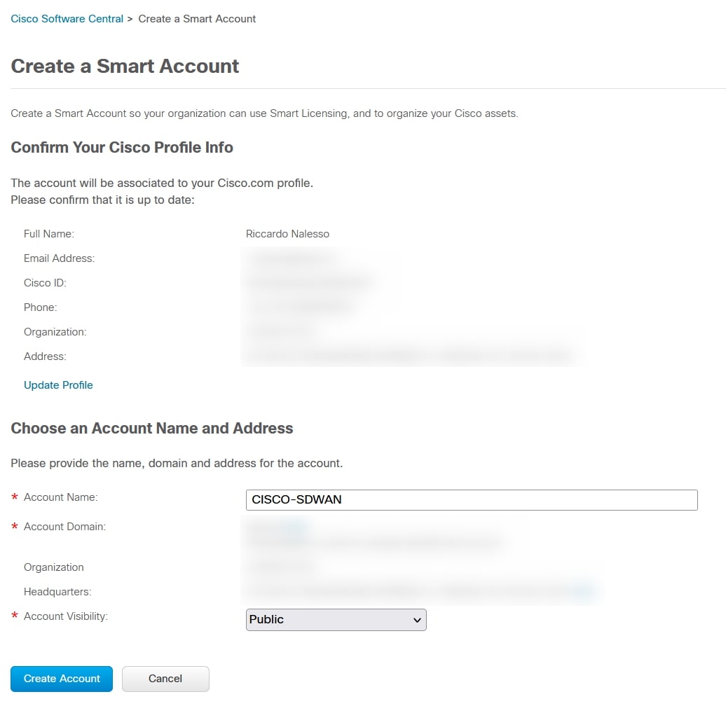
Login to Cisco Software Central
with your Cisco account.
Scroll down to “Smart Licensing” section and under “For customers” menu choose “New account” (I’m sorry but I have to hide all the sensitive data):
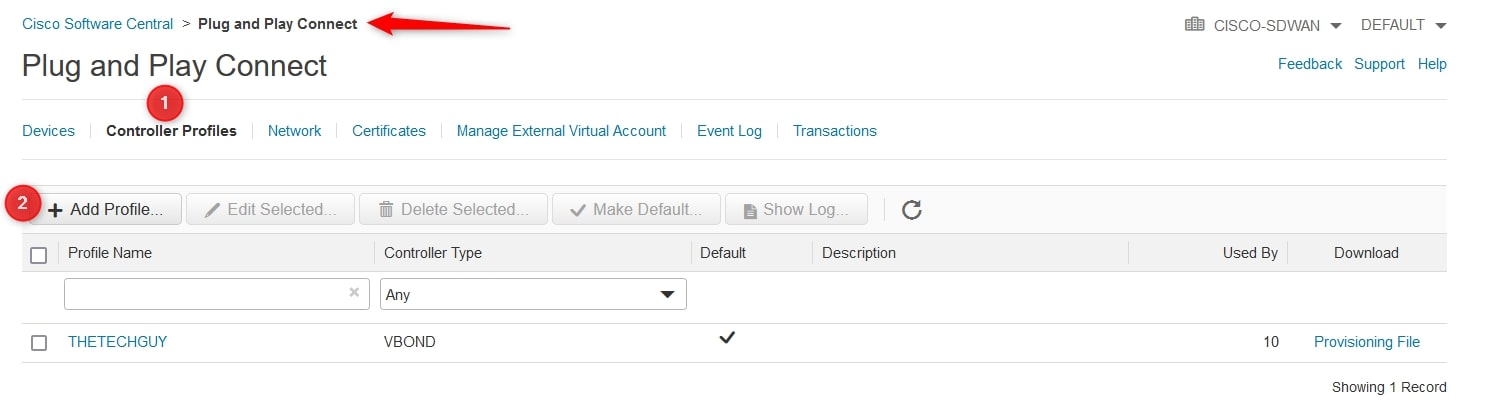
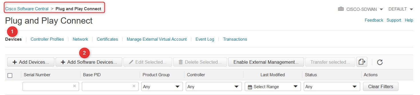
Now go to “Smart Licensing” section and under “For customers” menu choose “Network Plug and Play”. As you can see from the screenshot below the account name on the top-right of the screen is “CISCO-SDWAN”, this is the account that we created before.
In the new menu, go to “Controller Profiles” and click “Add Profile”:
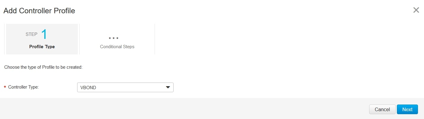
Step1:
Controller Type: VBOND
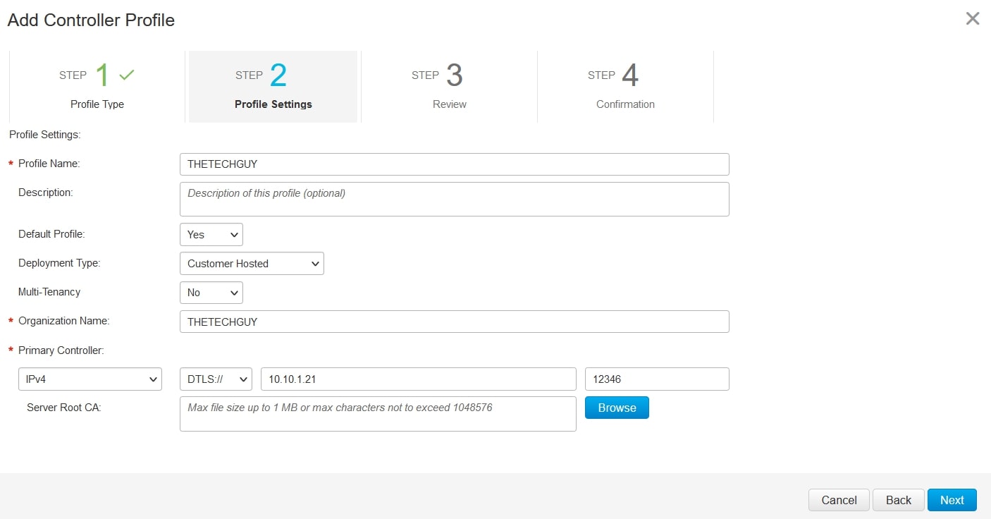
Step2:
Profile Name: Whatever your want, I choose “THETECHGUY”
Default Profile: Yes
Organization Name: for my lab I choose “THETECHGUY”.
❗ ❗ ❗ If you are using a different organization name please put here yours! ❗ ❗ ❗
The, review and confirm the controller profile creation.
Now, go to “Devices” and choose “Add Software Devices”:
Click again on “Add Software Devices” and on “Base PID” field digit “VEDGE-CLOUD-DNA”, then choose the quantity (max 25 devices for free) and the controller profile (created before):
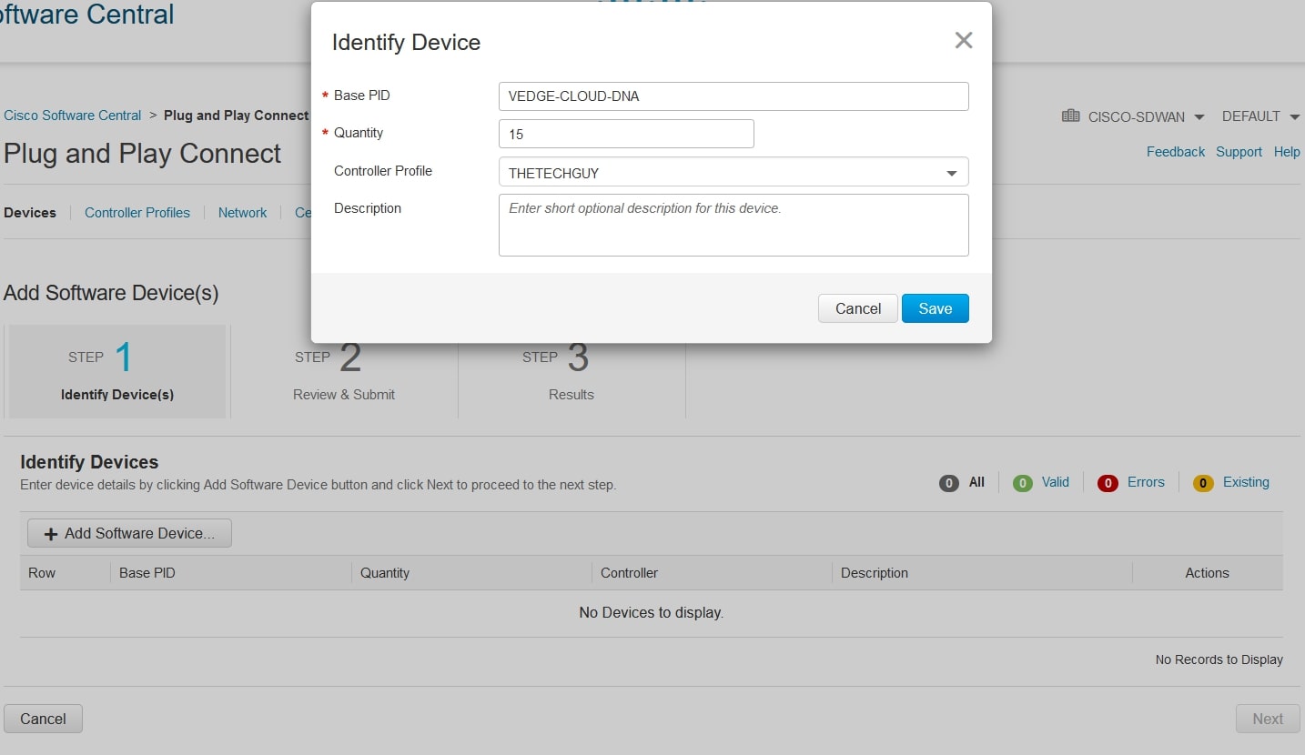
Then, click next and submit at the end.
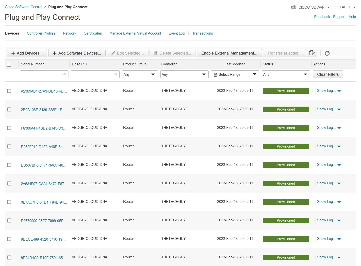
After a couple of seconds, you should receive an email from Cisco regarding your request and from the “Plug and Play Connect” menu this should be your view, with the “Status” column green for the provisioned devices:
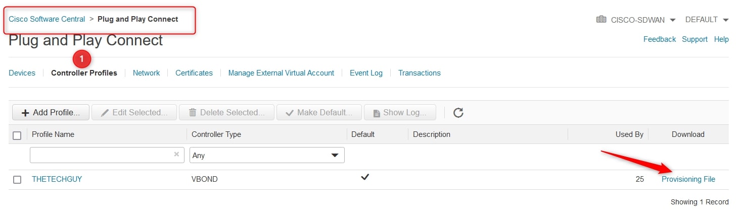
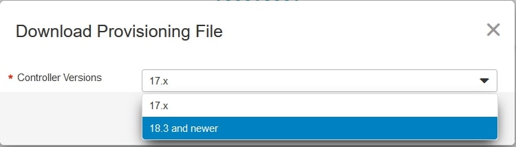
The final step is to download the “SerialFile.viptela”. To do that go to “Controller Profiles” and click on “Provisioning File”, an automatic download should start (after choosing the release):
Now that we have all the necessary files we can start!
Environment
EVE-NG
As you already know, I use EVE-NG
in order to create my labs. In my opinion, it’s the best clientless multivendor network emulation software. You can emulate multiple devices, releases and vendors thanks to EVE-NG.
Unfortunately, I’m still using the community version, but I’ll upgrade it to the Professional version during 2023 (here is the comparison between the two releases
)
My EVE-NG VM has the following resources:
- CPU: 8
- RAM: 64
- HDD: 60GB (Thick Provision Lazy Zeroed)
- vNIC with internet/mgmt access
Please note that it’s not mandatory to have this specs, the lab requires less resources. I have these resources because it’s not the only lab that I’m running on it.
Topology
In order to create this lab I used this topology (pretty common on my blog, except for IP addresses)
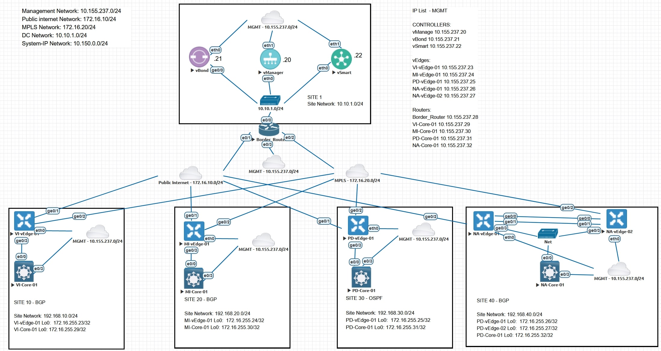
(Sorry for the huge amount of “MGMT” Cloud nodes)
I decided to create 4 sites: Vicenza, Milano, Padova, Napoli (yeah, they are Italian city names)
Why 4? For future blog posts, I can implement different templates, policies and configure TLOC Extension in Napoli. Cool, isn’t it? 😉
IP Addressing
I decided to use the following networks in my lab:
- Management Network: 10.155.237.0/24
- Public internet Network: 172.16.10/24
- MPLS Network: 172.16.20/24
- DC Network: 10.10.1.0/24
- Network for “system-ip”: 10.150.0.0/24
Design consideration: Do I need 254 IP addresses on each network? Of course not, but we are in a lab environment so it’s fine.
In this moment we can ignore the Site (192.168.x.0/24) and Loopback (172.16.255.x/24) networks because we’ll not use them now.
Version
I’m using the release 20.6.3, the suggested release at today (02/11/2023).
In the prerequisites section you can find all the direct download links 😊
Cisco SDWAN images EVE-NG
I’m not going to cover the import of the images on EVE-NG, but you can follow this guide
in order to successfully import and use the Cisco SDWAN images on your EVE-NG machine.
I used this guide and it’s complete with all the necessary tasks.
Cisco SDWAN initial configuration
Here you can find the initial/basic controllers configurations, remember that the “organization-name” parameter must match in all the devices
vBond
config
system
host-name vBond
system-ip 10.150.0.21
site-id 1
organization-name THETECHGUY
vbond 10.10.1.21 local
vpn 0
interface ge0/0
ip add 10.10.1.21/24
no shut
no tunnel-interface
exit
ip route 0.0.0.0/0 10.10.1.254
exit
vpn 512
interface eth0
ip add 10.155.237.21/24
no shut
exit
ip route 0.0.0.0/0 10.155.237.254
exit
commit and-quit
After that I recommend you to reload the device.
vSmart
config
system
host-name vSmart
system-ip 10.150.0.22
site-id 1
organization-name THETECHGUY
vbond 10.10.1.21
vpn 0
interface eth0
ip add 10.10.1.22/24
no shut
no tunnel-interface
exit
ip route 0.0.0.0/0 10.10.1.254
exit
vpn 512
interface eth1
ip add 10.155.237.22/24
no shut
exit
ip route 0.0.0.0/0 10.155.237.254
exit
commit and-quit
After that I recommend you to reload the device.
vManage
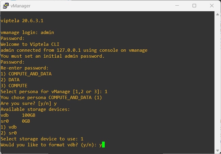
During the first boot you have to select the “persona” (choose option 1) and the “storage device” (should be “vdb”, if you followed the image import correctly):
Basic Config
config
system
host-name vManage
system-ip 10.150.0.20
site-id 1
organization-name THETECHGUY
vbond 10.10.1.21
vpn 0
interface eth0
ip add 10.10.1.20/24
no shut
no tunnel-interface
exit
ip route 0.0.0.0/0 10.10.1.254
exit
vpn 512
interface eth1
ip add 10.155.237.20/24
no shut
exit
ip route 0.0.0.0/0 10.155.237.254
exit
commit and-quit
After that I recommend you to reload the device.
Wait some minutes and then browse the vManage eth1 IP Address (MGMT IP), login with the default username/password (admin/admin), then the vManage will ask you to change the password.
Cisco legacy device configuration
Border_Router
en
conf t
alias exec c configure terminal
hostname Border_Router
int e0/0
no shut
descr LAN
ip add 10.10.1.254 255.255.255.0
exit
int e0/3
no shut
descr MGMT
ip add 10.155.237.28 255.255.255.0
duplex full
exit
ip domain-name thetechguy.it
no ip domain lookup
crypto key generate rsa modul 2048
username admin privile 15 secret admin
line vty 0 4
login local
transport in ssh
exit
ip route 0.0.0.0 0.0.0.0 10.155.237.254
int e0/1
descr Public_Internet
ip add 172.16.10.254 255.255.255.0
no shut
int e0/2
descr MPLS
ip add 172.16.20.254 255.255.255.0
no shut
end
wr
After that I recommend you to reload the device.
VI-Core-01
en
conf t
alias exec c configure terminal
hostname VI-CORE-01
int e0/0
no shut
descr LAN
exit
int e0/3
no shut
no swi
descr MGMT
ip add 10.155.237.29 255.255.255.0
exit
ip domain-name thetechguy.it
no ip domain lookup
crypto key generate rsa modul 2048
username admin privile 15 secret admin
line vty 0 4
login local
transport in ssh
exit
ip route 0.0.0.0 0.0.0.0 10.155.237.254
end
wr
After that I recommend you to reload the device.
MI-Core-01
en
conf t
alias exec c configure terminal
hostname MI-CORE-01
int e0/0
no shut
descr LAN
exit
int e0/3
no shut
no swi
descr MGMT
ip add 10.155.237.30 255.255.255.0
exit
ip domain-name thetechguy.it
no ip domain lookup
crypto key generate rsa modul 2048
username admin privile 15 secret admin
line vty 0 4
login local
transport in ssh
exit
ip route 0.0.0.0 0.0.0.0 10.155.237.254
end
wr
After that I recommend you to reload the device.
PD-Core-01
en
conf t
alias exec c configure terminal
hostname PD-CORE-01
int e0/0
no shut
descr LAN
exit
int e0/3
no shut
no swi
descr MGMT
ip add 10.155.237.31 255.255.255.0
exit
ip domain-name thetechguy.it
no ip domain lookup
crypto key generate rsa modul 2048
username admin privile 15 secret admin
line vty 0 4
login local
transport in ssh
exit
ip route 0.0.0.0 0.0.0.0 10.155.237.254
end
wr
After that I recommend you to reload the device.
NA-Core-01
en
conf t
alias exec c configure terminal
hostname NA-CORE-01
int e0/0
no shut
descr LAN
exit
int e0/3
no shut
no swi
descr MGMT
ip add 10.155.237.32 255.255.255.0
exit
ip domain-name thetechguy.it
no ip domain lookup
crypto key generate rsa modul 2048
username admin privile 15 secret admin
line vty 0 4
login local
transport in ssh
exit
ip route 0.0.0.0 0.0.0.0 10.155.237.254
end
wr
After that I recommend you to reload the device.
Reachability test
From Border Router (Testing MGMT interface)
tclsh
foreach address {
10.155.237.20
10.155.237.21
10.155.237.22
10.155.237.28
10.155.237.29
10.155.237.30
10.155.237.31
10.155.237.32
} { ping $address repeat 3 size 1500 }
Result should be something like that:
Type escape sequence to abort.
Sending 3, 1500-byte ICMP Echos to 10.155.237.20, timeout is 2 seconds:
!!!
Success rate is 100 percent (3/3), round-trip min/avg/max = 1/1/2 ms
Type escape sequence to abort.
Sending 3, 1500-byte ICMP Echos to 10.155.237.21, timeout is 2 seconds:
!!!
Success rate is 100 percent (3/3), round-trip min/avg/max = 1/1/1 ms
Type escape sequence to abort.
Sending 3, 1500-byte ICMP Echos to 10.155.237.22, timeout is 2 seconds:
!!!
Success rate is 100 percent (3/3), round-trip min/avg/max = 1/1/1 ms
Type escape sequence to abort.
Sending 3, 1500-byte ICMP Echos to 10.155.237.28, timeout is 2 seconds:
!!!
Success rate is 100 percent (3/3), round-trip min/avg/max = 4/4/4 ms
Type escape sequence to abort.
Sending 3, 1500-byte ICMP Echos to 10.155.237.29, timeout is 2 seconds:
!!!
Success rate is 100 percent (3/3), round-trip min/avg/max = 1/1/1 ms
Type escape sequence to abort.
Sending 3, 1500-byte ICMP Echos to 10.155.237.30, timeout is 2 seconds:
!!!
Success rate is 100 percent (3/3), round-trip min/avg/max = 1/1/1 ms
Type escape sequence to abort.
Sending 3, 1500-byte ICMP Echos to 10.155.237.31, timeout is 2 seconds:
!!!
Success rate is 100 percent (3/3), round-trip min/avg/max = 1/1/2 ms
Type escape sequence to abort.
Sending 3, 1500-byte ICMP Echos to 10.155.237.32, timeout is 2 seconds:
!!!
Success rate is 100 percent (3/3), round-trip min/avg/max = 1/1/1 ms
Please note that the previous ping test should be done also from your laptop because you need SSH access to the devices.
From Border Router (Testing LAN interface)
tclsh
foreach address {
10.10.1.20
10.10.1.21
10.10.1.22
} { ping $address repeat 3 size 1500 }
Result should be something like that:
Type escape sequence to abort.
Sending 3, 1500-byte ICMP Echos to 10.10.1.20, timeout is 2 seconds:
!!!
Success rate is 100 percent (3/3), round-trip min/avg/max = 1/2/4 ms
Type escape sequence to abort.
Sending 3, 1500-byte ICMP Echos to 10.10.1.21, timeout is 2 seconds:
!!!
Success rate is 100 percent (3/3), round-trip min/avg/max = 28/31/34 ms
Type escape sequence to abort.
Sending 3, 1500-byte ICMP Echos to 10.10.1.22, timeout is 2 seconds:
!!!
Success rate is 100 percent (3/3), round-trip min/avg/max = 1/1/2 ms
Great, we achieve IP reachability!
Now, move on 😊
Configuration of certificates
This is a very tricky and complex part, in my opinion the hardest part of the lab. Please pay attention to all the steps, if you have any doubts you can reach me out on Twitter , LinkedIn or via email
❗ Important1: I’m using my laptop as CA! ❗
❗ Important2: I installed WSL on my Windows machine in order to create/sign certificates. Windows Subsystem for Linux (WLS) is a feature of Windows that allows developers to run a Linux environment without the need for a separate virtual machine or dual booting. ❗
TIP: You can generate the ROOT CA and sign the CSRs directly in the vshell (commonly on the vManage). It means that you don’t have to download/install WSL if you don’t have/want it
Let’s start!
Create a certificate on your machine
openssl genrsa -out CA.key 2048

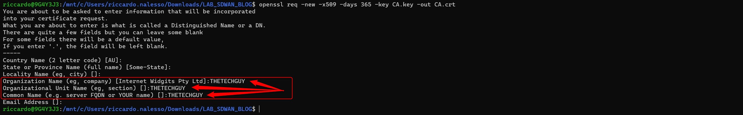
Please make sure to insert your organization-id in this phase, if you’re using mine organization-id name you can just use the following values:
openssl req -new -x509 -days 365 -key CA.key -out CA.crt
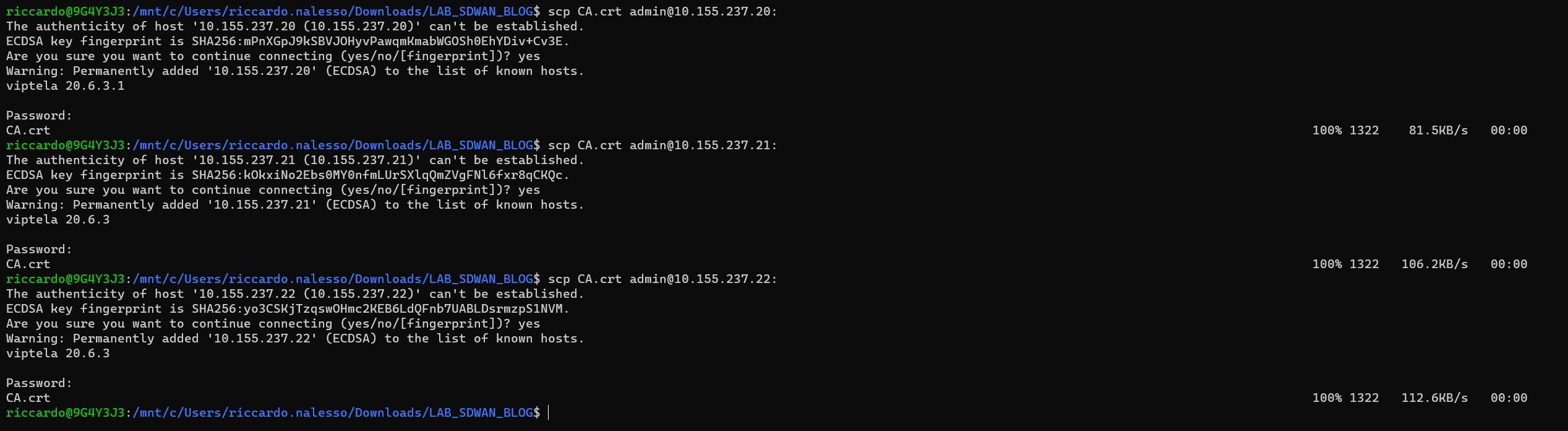
Now, let’s copy the certificate from your PC to the controllers using SCP
scp CA.crt admin@<controller_ip_address>:
If you’re using the same IP addresses of my lab, here are the commands:
scp CA.crt admin@10.155.237.20:
scp CA.crt admin@10.155.237.21:
scp CA.crt admin@10.155.237.22:
SSH to the controllers and verify that the “CA.crt” file is here:
vshell
ls
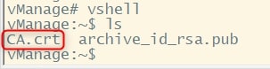
Then, install it:
request root-cert-chain install /home/admin/CA.crt
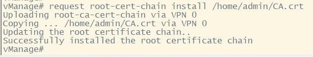
Repeat it for all the controllers and after that login to the vManage GUI.
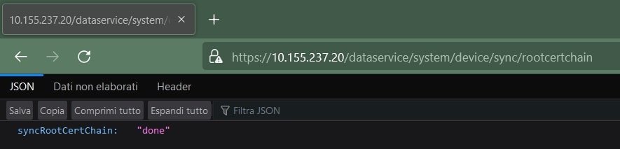
When you are in the vManage main dashboard, open another tab in your web and type:
https://<vManage_ip_address>/dataservice/system/device/sync/rootcertchain
If you’re using the same IP addresses of my lab, here is the URL:
https://10.155.237.20/dataservice/system/device/sync/rootcertchain
This procedure allows us to fix the RootCA. The output should be:
Great!
Now configure Organization name and vBond IP using the “edit” button under:
Administration > Settings
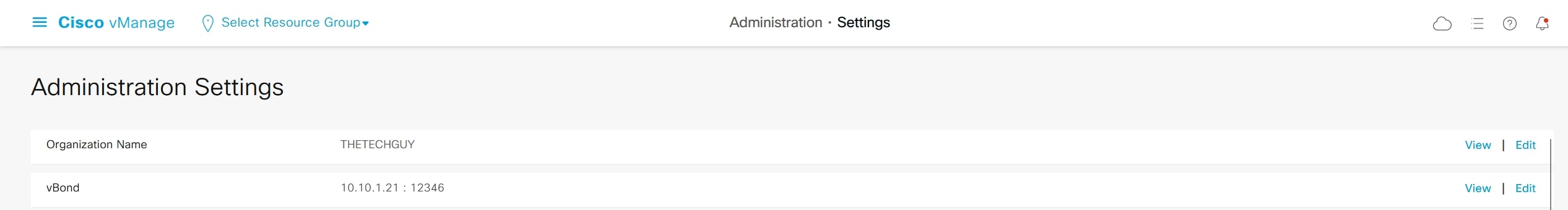
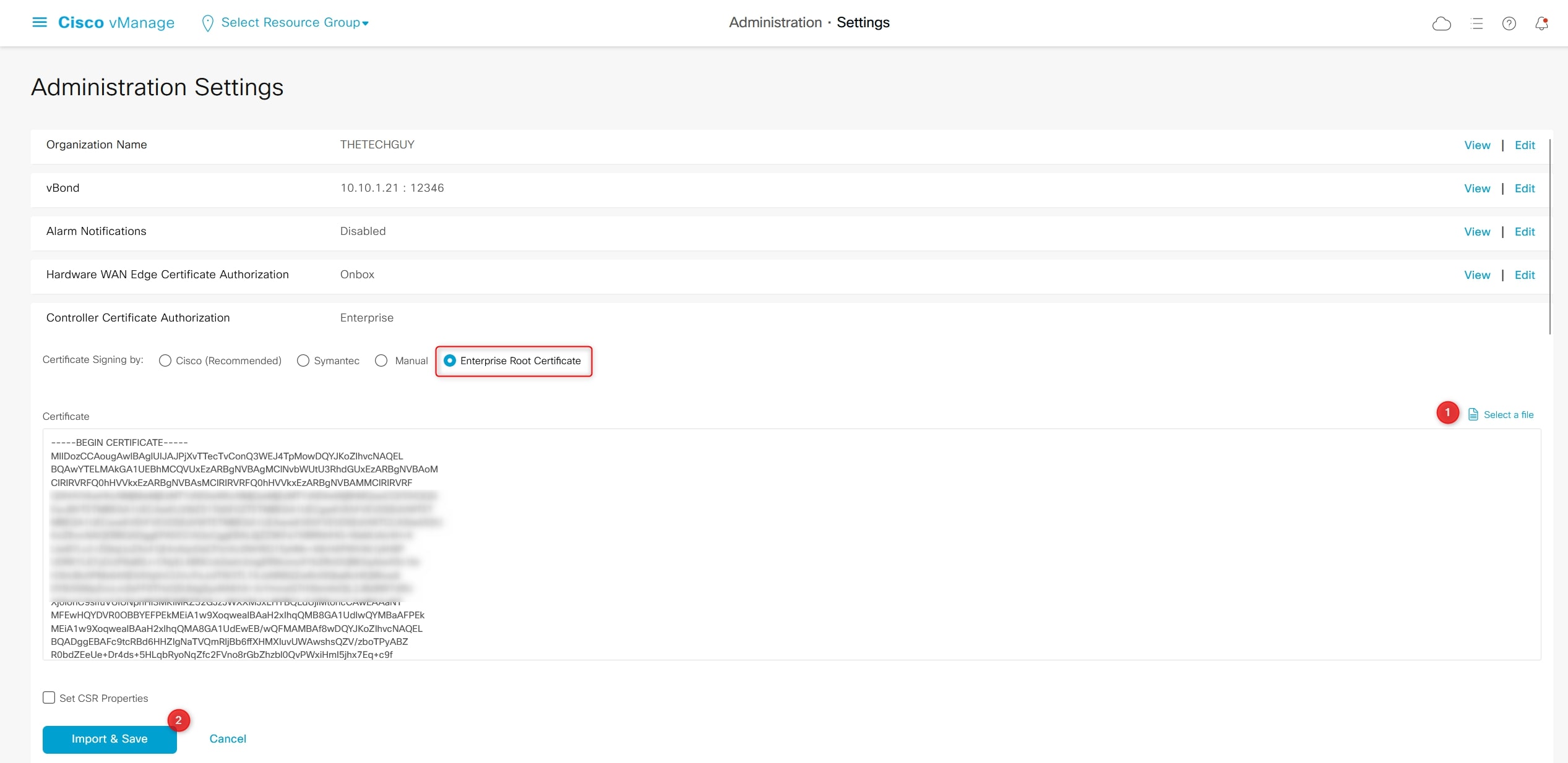
Now on “Controller Certificate Authorization” change the default value “Cisco” with “Enterprise Root Certificate”.
Click “Select a file”, select the “CA.crt” file on your computer. Then click on “Import and Save”.
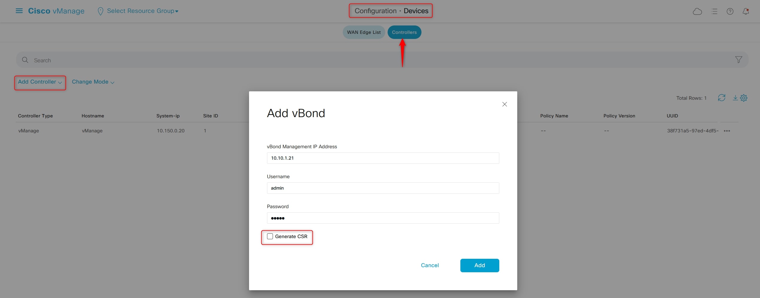
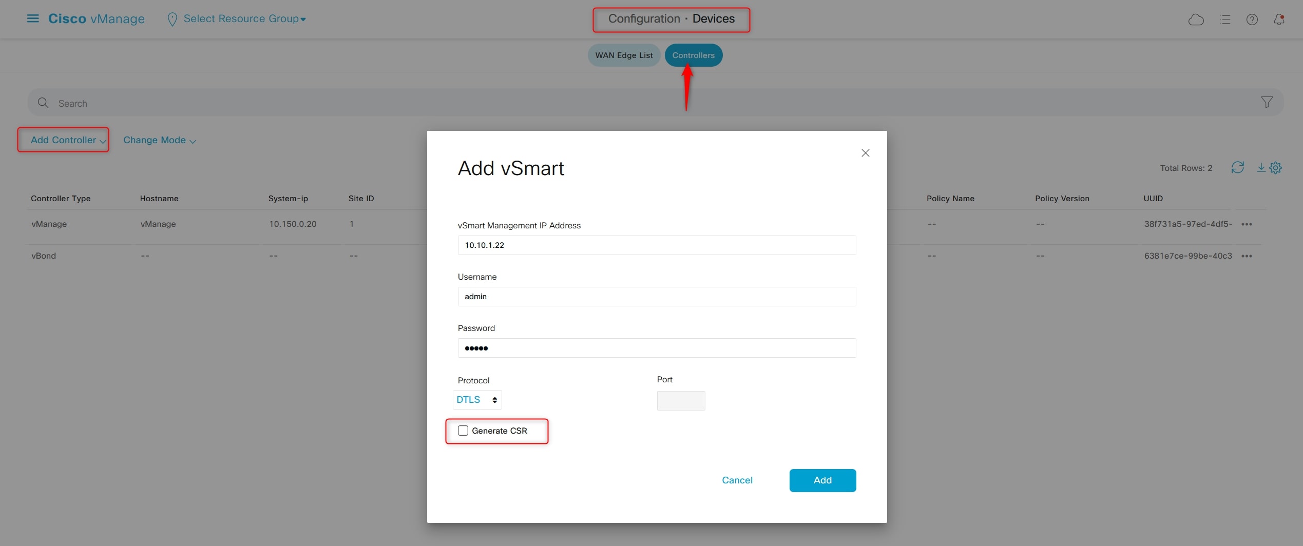
Perfect, now let’s add the vBond and vSmart controllers to vManage:
Configuration > Devices > Controllers > Add Controller
Do not generate CSR in this phase
Now go to:
Configuration > Certificates > Controllers
And generate the CSR for each controller and download it
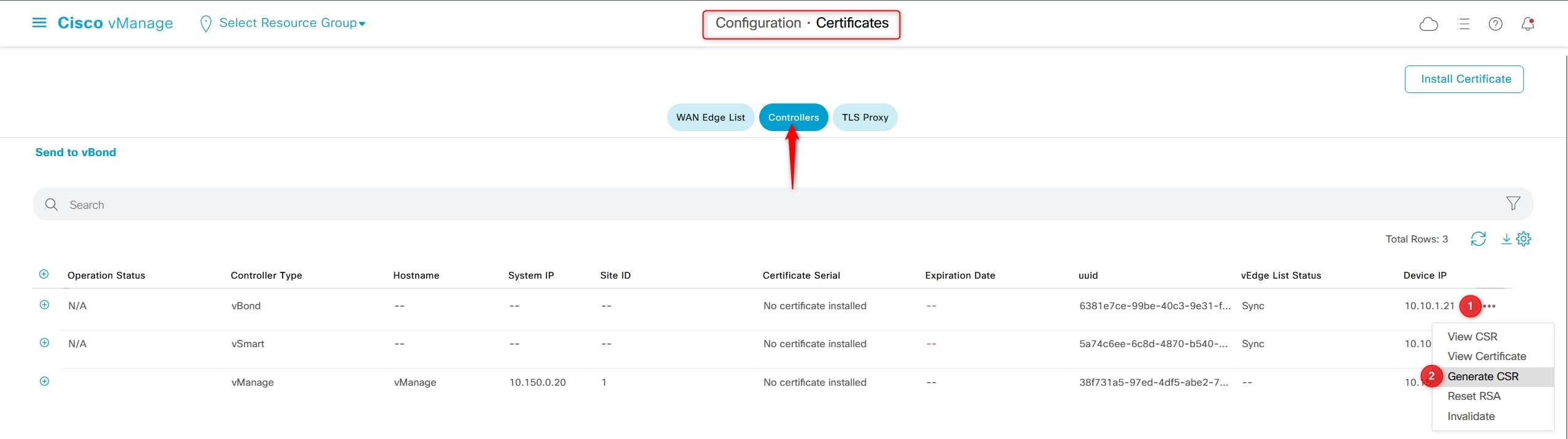
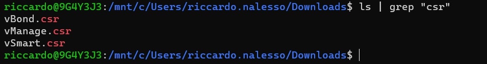
When you download it, remember to change the name of the file with “vBond.csr”, “vSmart.csr” and “vManage.csr” (it’s not manadatory, of course, but it will help you in recognize the file).
In your Download folder you should have these files:
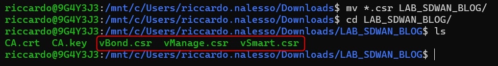
Move these files in the same folder where CA.crt and CA.key are stored:
Now, generate the certificates:
openssl x509 -req -in vSmart.csr -CA CA.crt -CAkey CA.key -CAcreateserial -out vSmart.crt -days 2000 -sha256
openssl x509 -req -in vBond.csr -CA CA.crt -CAkey CA.key -CAcreateserial -out vBond.crt -days 2000 -sha256
openssl x509 -req -in vManage.csr -CA CA.crt -CAkey CA.key -CAcreateserial -out vManage.crt -days 2000 -sha256
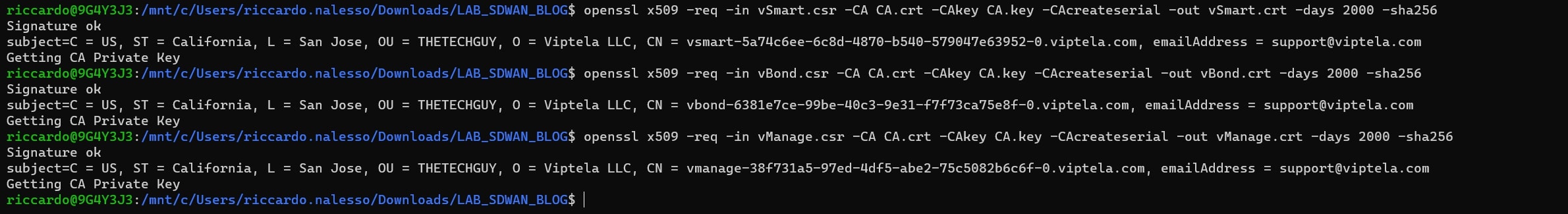
In the folder you should have now these files:

Great, move to vManage GUI under:
Configuration > Certificates > Controllers
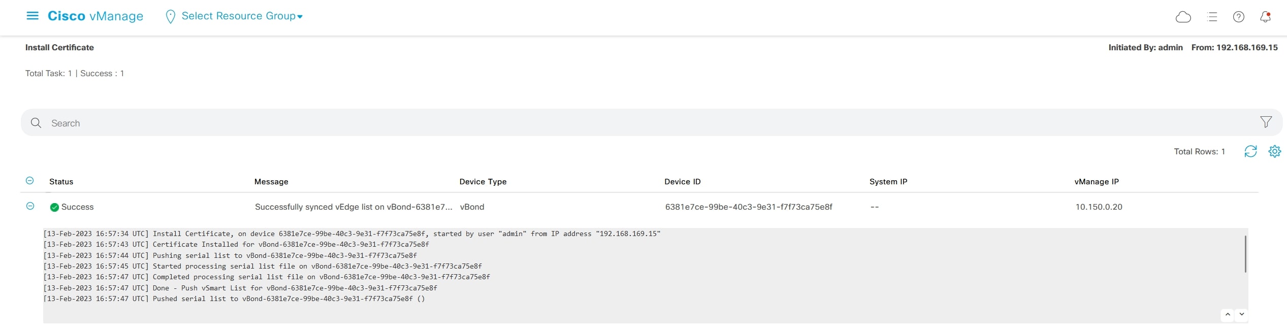
And press “Install Certificate” (top-right of the page) and select “vBond.crt”
The vManage will redirect you on this page in order to follow the operation
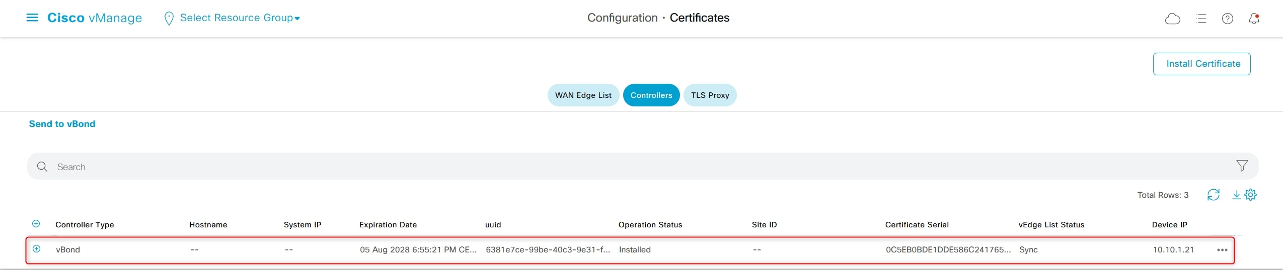
Go again on:
Configuration > Certificates > Controllers
And verity that vBond has the certificate installed
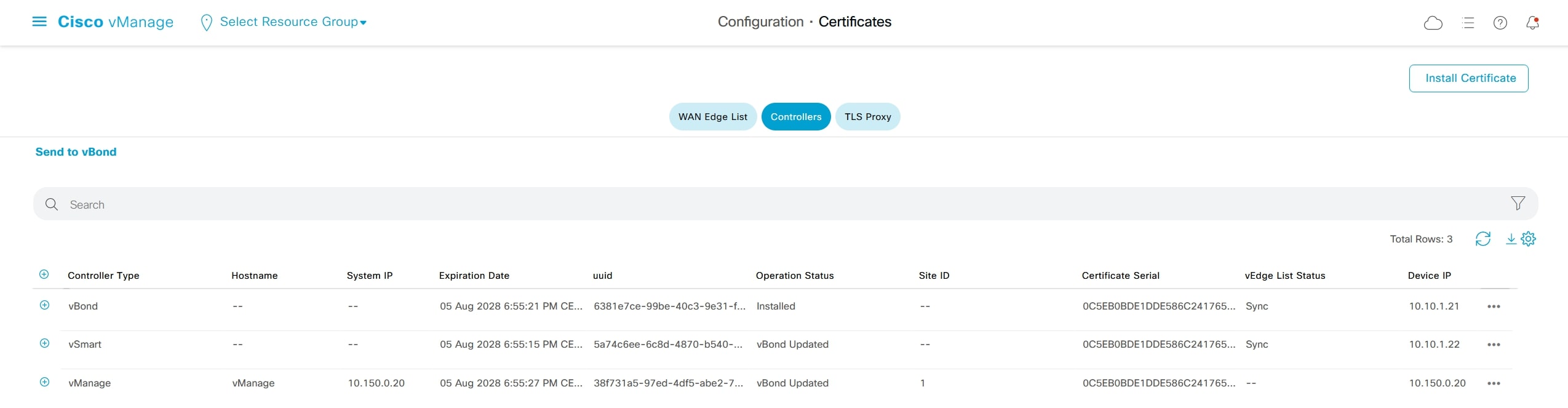
Do the same procedure for vManage and vSmart. This is the final result:
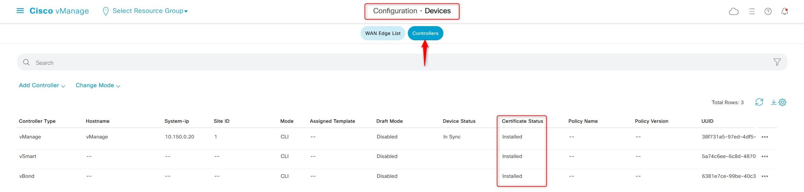
Under:
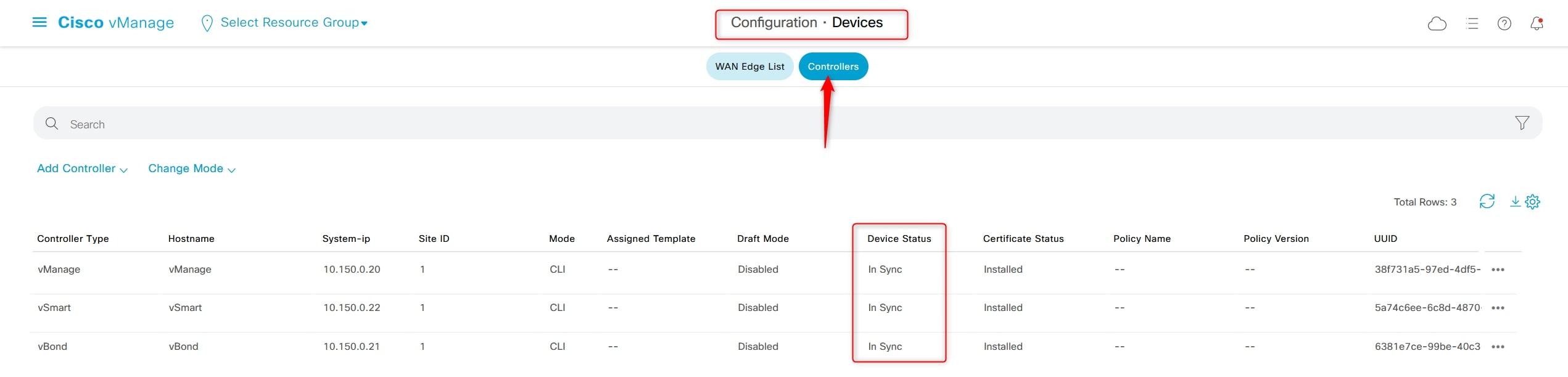
Configuration > Devices > Controllers
Verify that the “Certificate Status” is “Installed” and the “Device Status” is empty (except for vManage):
Now, move on controllers CLI and enable the tunnel under VPN0 section. These links are the link connected to the Border_Router from topology point of view:
VPN0 Tunnel configuration
Controllers
vBond:
config
vpn 0
interface ge0/0
tunnel-interface
encapsulation ipsec
commit and-quit
vManage and vSmart:
config
vpn 0
interface eth0
tunnel-interface
commit and-quit
Go back to GUI:
Configuration > Devices > Controllers
And now you will see that the “Device Status” is “In Sync” for all the controllers
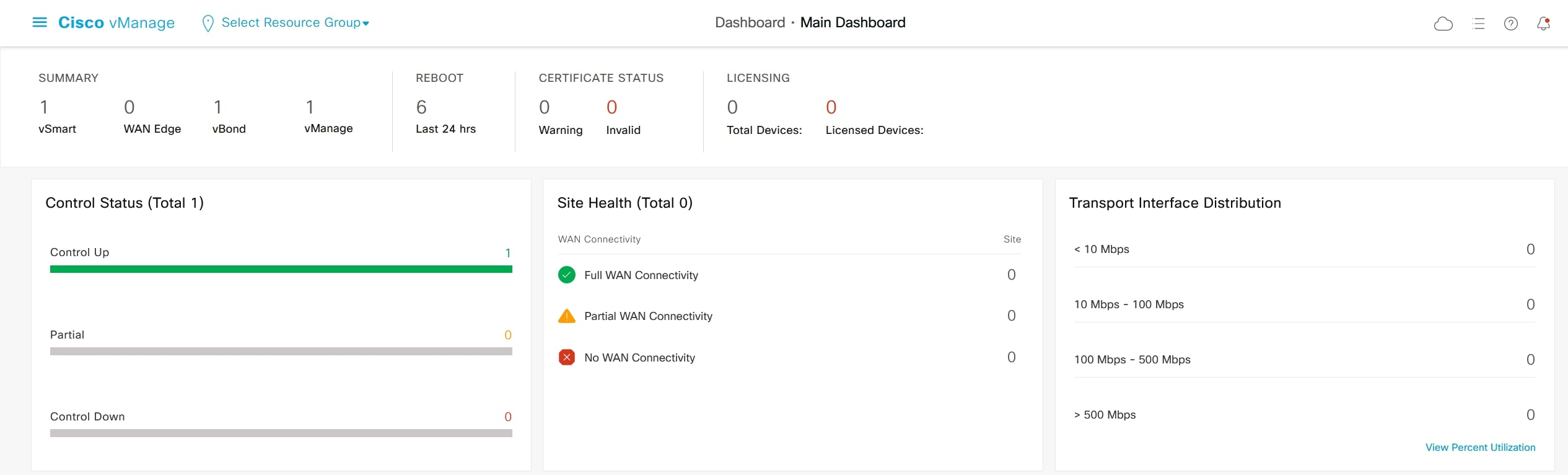
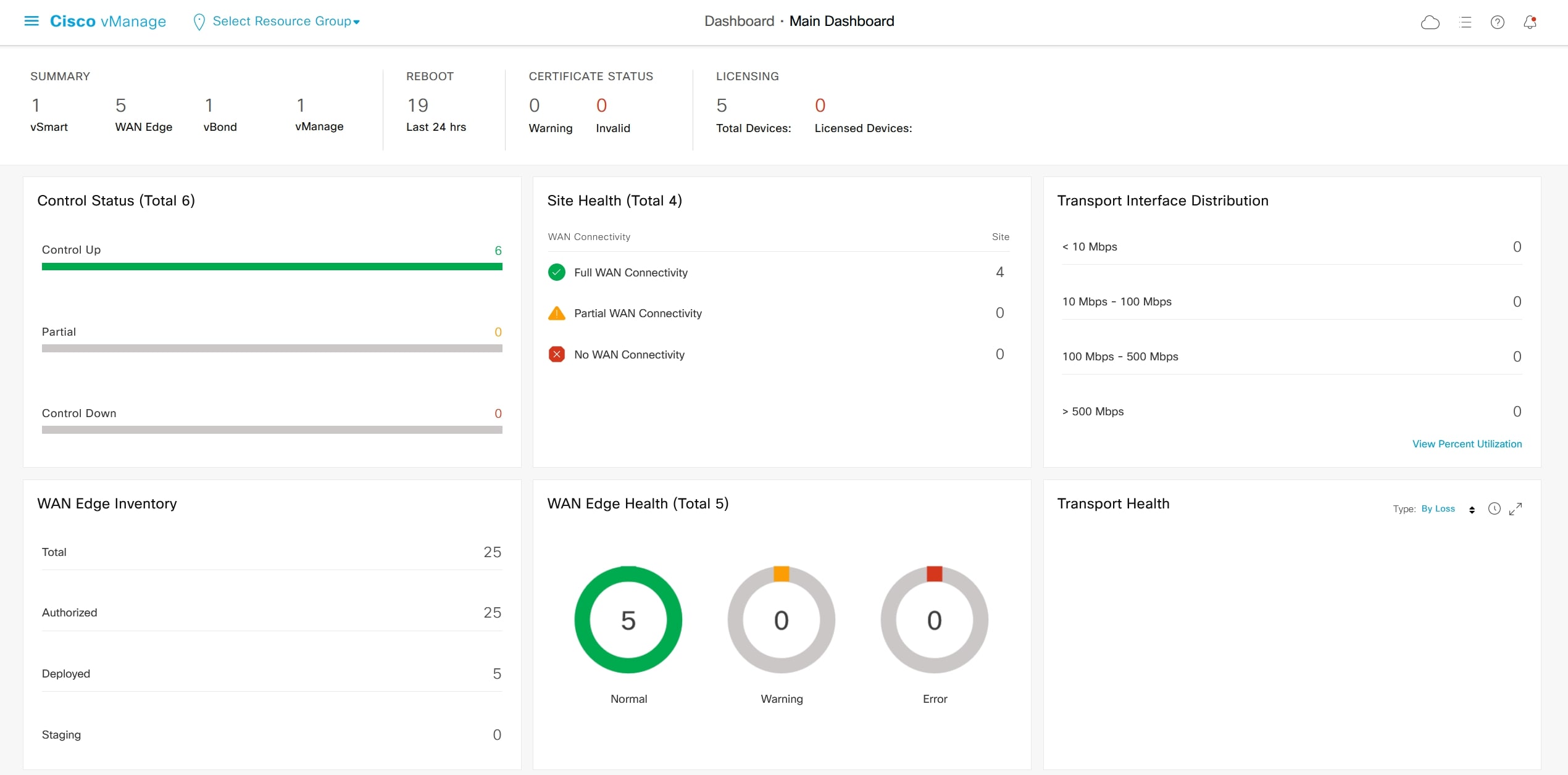
Go to the main dashboard:
Dashboard > Main Dashboard
And verify that vBond, vManage and vSmart are ok. GUI:
vSmart and vManage CLI checks:
show control connections


vBond CLI checks:
show orchestrator connections
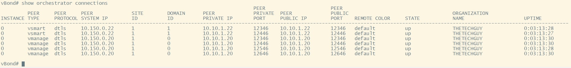
GREAT! Now move on with vEdge configurations 😊
Vicenza vEdge
config
system
host-name VI-vEdge-01
system-ip 10.150.0.111
site-id 10
organization-name THETECHGUY
vbond 10.10.1.21
vpn 0
interface ge0/0
no ip add
shut
no tunnel-interface
interface ge0/3
no ip add
no tunnel-interface
interface ge0/1
no shut
ip add 172.16.10.11/24
tunnel-interface
allow-service all
encapsulation ipsec
exit
ip route 0.0.0.0/0 172.16.10.254
exit
vpn 512
interface eth0
no shut
ip add 10.155.237.23/24
exit
ip route 0.0.0.0/0 10.155.237.254
commit and-quit
After that I recommend you to reload the device.
Milano vEdge
config
system
host-name MI-vEdge-01
system-ip 10.150.0.121
site-id 20
organization-name THETECHGUY
vbond 10.10.1.21
vpn 0
interface ge0/0
no ip add
shut
no tunnel-interface
interface ge0/3
no ip add
no tunnel-interface
interface ge0/1
no shut
ip add 172.16.10.21/24
tunnel-interface
allow-service all
encapsulation ipsec
exit
ip route 0.0.0.0/0 172.16.10.254
exit
vpn 512
interface eth0
no shut
ip add 10.155.237.24/24
exit
ip route 0.0.0.0/0 10.155.237.254
commit and-quit
After that I recommend you to reload the device.
Padova vEdge
config
system
host-name PD-vEdge-01
system-ip 10.150.0.131
site-id 30
organization-name THETECHGUY
vbond 10.10.1.21
vpn 0
interface ge0/0
no ip add
shut
no tunnel-interface
interface ge0/3
no ip add
no tunnel-interface
interface ge0/1
no shut
ip add 172.16.10.31/24
tunnel-interface
allow-service all
encapsulation ipsec
exit
ip route 0.0.0.0/0 172.16.10.254
exit
vpn 512
interface eth0
no shut
ip add 10.155.237.25/24
exit
ip route 0.0.0.0/0 10.155.237.254
commit and-quit
After that I recommend you to reload the device.
Napoli vEdge-01
config
system
host-name NA-vEdge-01
system-ip 10.150.0.141
site-id 40
organization-name THETECHGUY
vbond 10.10.1.21
vpn 0
interface ge0/0
no ip add
shut
no tunnel-interface
interface ge0/3
no ip add
no tunnel-interface
interface ge0/2
no shut
ip add 172.16.10.41/24
tunnel-interface
allow-service all
encapsulation ipsec
exit
ip route 0.0.0.0/0 172.16.10.254
exit
vpn 512
interface eth0
no shut
ip add 10.155.237.26/24
exit
ip route 0.0.0.0/0 10.155.237.254
commit and-quit
After that I recommend you to reload the device.
Napoli vEdge-02
config
system
host-name NA-vEdge-02
system-ip 10.150.0.142
site-id 40
organization-name THETECHGUY
vbond 10.10.1.21
vpn 0
interface ge0/0
no ip add
shut
no tunnel-interface
interface ge0/3
no ip add
no tunnel-interface
interface ge0/2
no shut
ip add 172.16.20.42/24
tunnel-interface
allow-service all
encapsulation ipsec
exit
ip route 0.0.0.0/0 172.16.20.254
exit
vpn 512
interface eth0
no shut
ip add 10.155.237.27/24
exit
ip route 0.0.0.0/0 10.155.237.254
commit and-quit
After that I recommend you to reload the device.
Reachability test
From vSmart (or another controller) ping the vEdges:
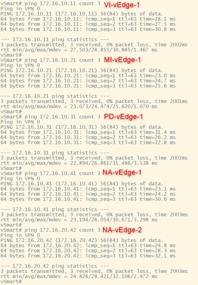
Perfect. Now we can proceed.
vEdge Certificates
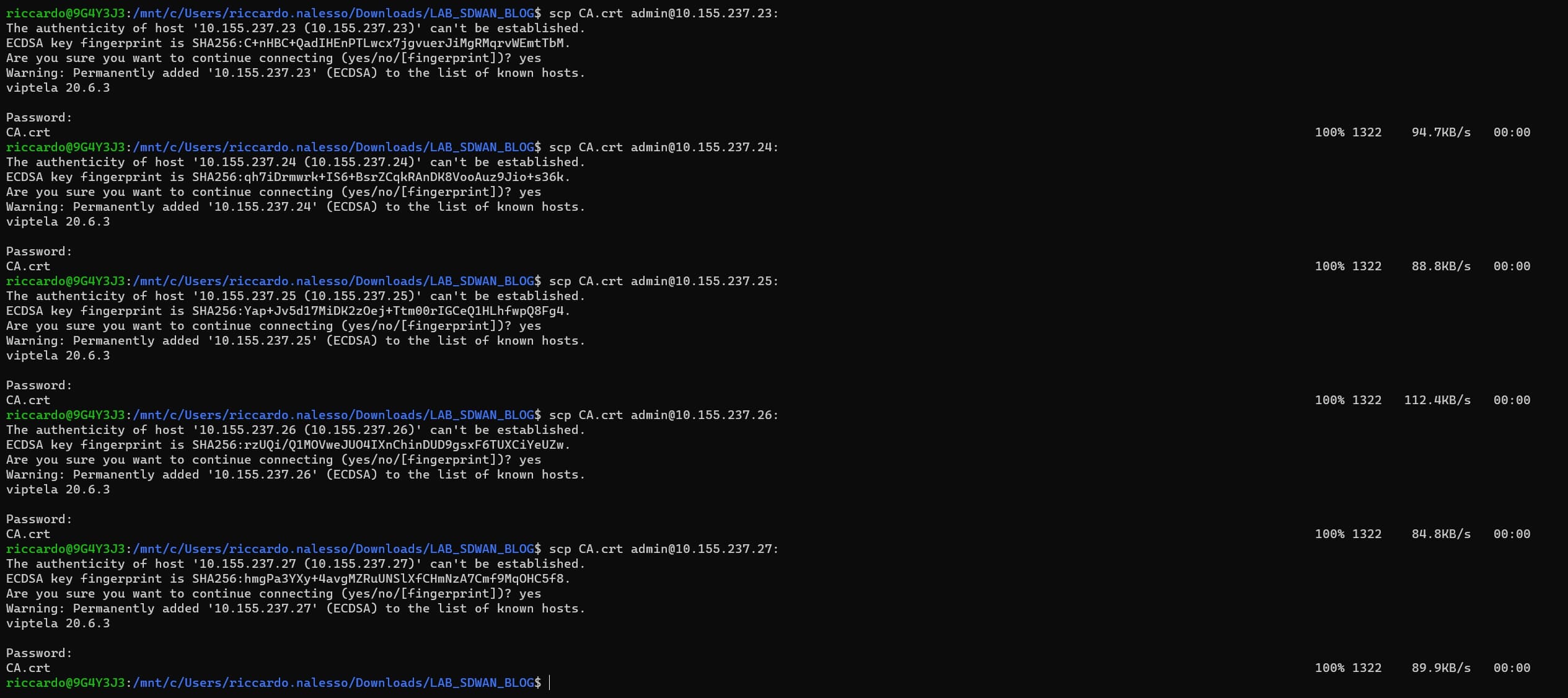
Let’s copy the “CA.crt” file into vEdges using SCP
scp CA.crt admin@<ip_address>:
If you’re using the same IP addresses of my lab, here are the commands:
scp CA.crt admin@10.155.237.23:
scp CA.crt admin@10.155.237.24:
scp CA.crt admin@10.155.237.25:
scp CA.crt admin@10.155.237.26:
scp CA.crt admin@10.155.237.27:
SSH to the vEdges and check if the file is inside:
vshell
ls
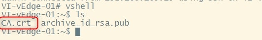
Here you should find the “CA.crt” file.
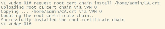
Now install it by using the following command:
request root-cert-chain install /home/admin/CA.crt
Upload vEdges list to vManage
❗ IF YOU SKIPPED THE BEGINNING OF THE GUIDE, PLEASE RETURN AT THE “PREREQUISITES” CHAPTER AND CREATE YOUR “SerialFile.viptela” FILE ❗
This is another important phase. There are several way to onboard Cisco SDWAN WAN Edge devices into the enterprise SDWAN Infrastructure.
Onboarding WAN Edge devices requires the SDWAN controllers to learn the authorized device list. The whitelist device list is retrieved from the Plug and Play (PnP) Connect portal and made available to the vManage controller either by manually uploading or syncing the vManage directly with the PnP connect portal. The whitelist device list is than sent to other SDWAN controllers from vManage.
I decided to go with the manual procedure, by downloading the file from the Plug and Play (PnP) Connect portal and uploading it to the vManage.
Here you can find a very useful document talking about this part: https://www.cisco.com/c/dam/en/us/td/docs/solutions/CVD/SDWAN/sdwan-wan-edge-onboarding-deploy-guide-2020nov.pdf
Upload the SerialFile.viptela file to vManage
Let’s start!
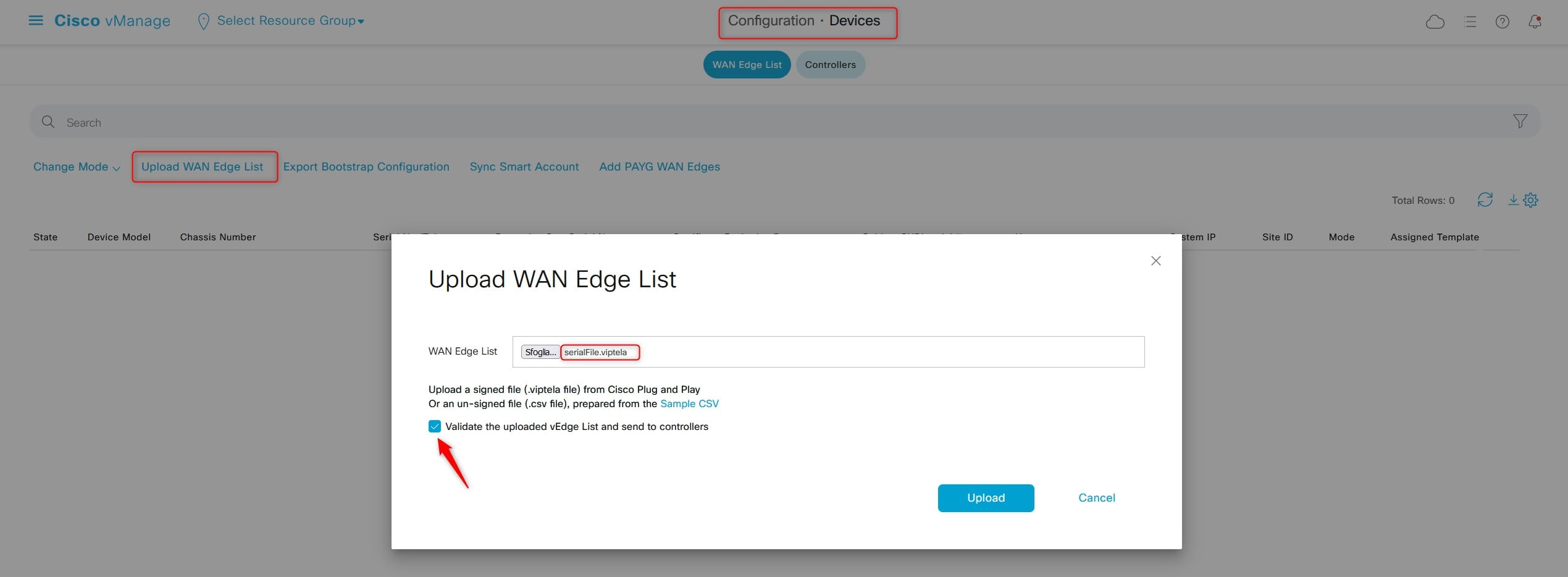
Go to:
Configuration > Devices > WAN Edge List
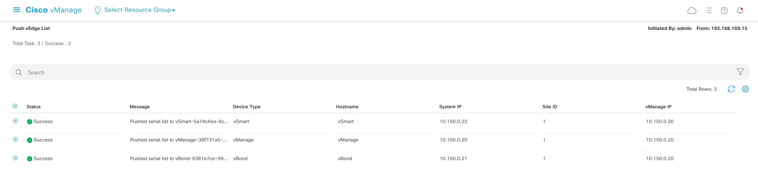
And click “Upload WAN Edge List”, choose the file that you previously have downloaded, flag “validate the uploaded vEdge List and send to controllers”, then click “Upload”:
The list will now be pushed to controllers:
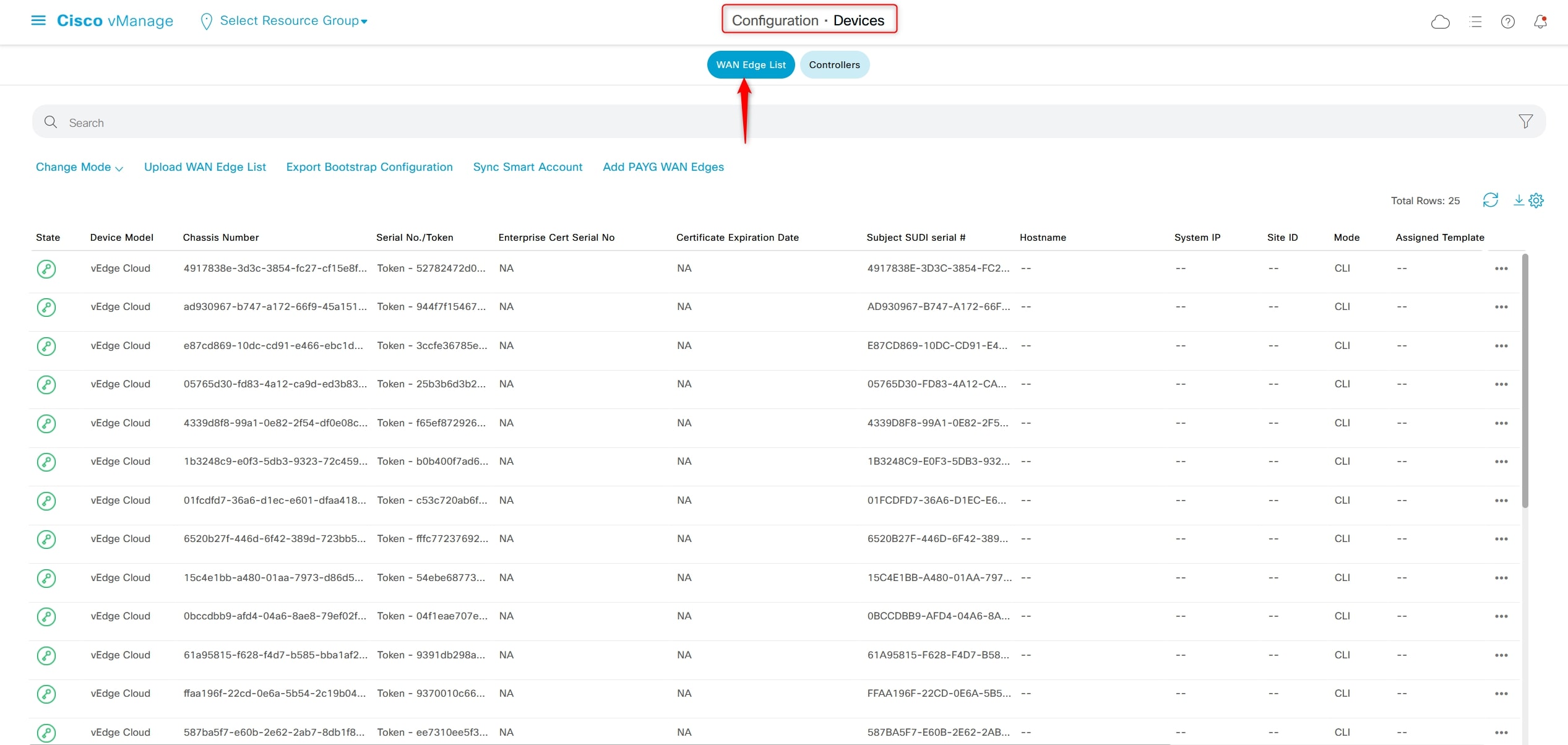
Now you should be able to see all the list of vEdge uploaded under:
Configuration > Devices > WAN Edge List
Onboarding vEdge
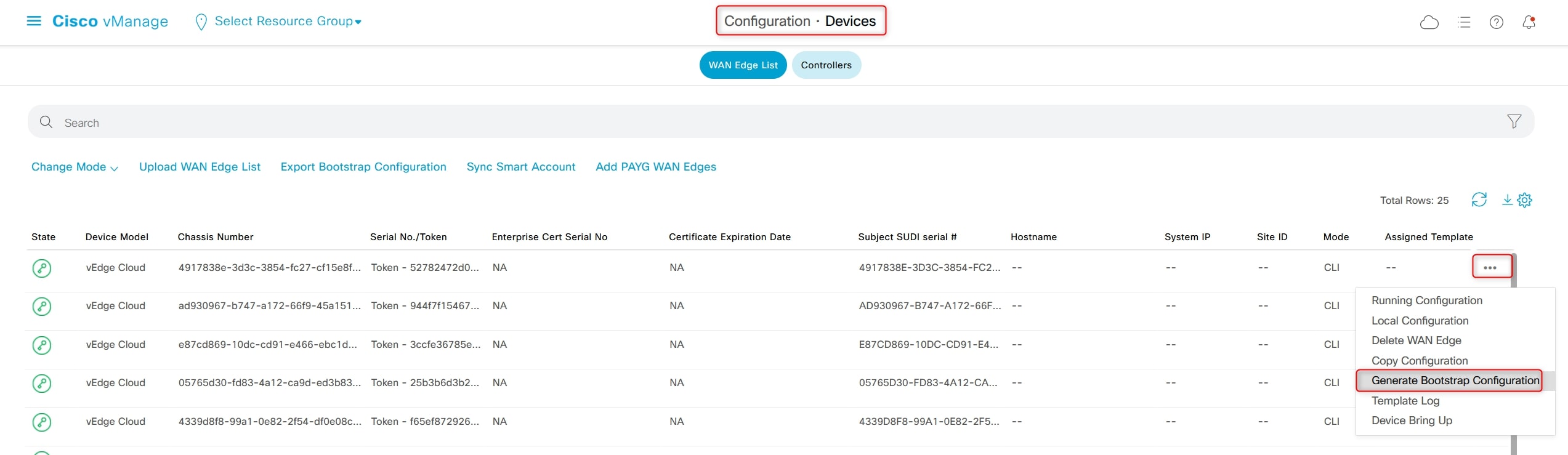
From:
Configuration> Devices > WAN Edge List
Click the three dots “…” at the right and choose “Generate Bootstrap Configuration”
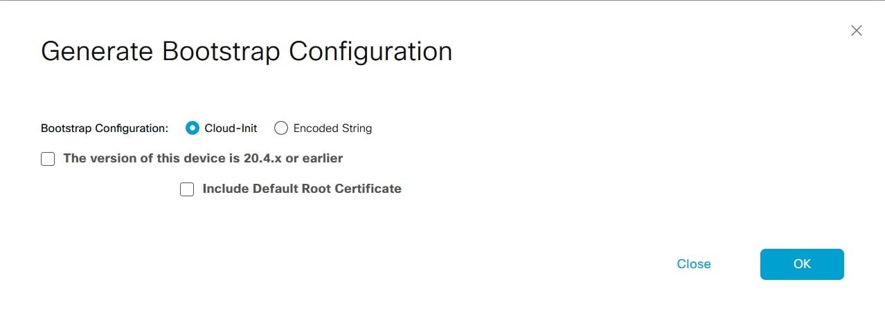
Deselect “Include Default Root Certificate” and select the first option if you’re running vEdges 20.4.x or earlier (not my case, I’m using 20.6.3) and click “OK”:
Then, copy the field “path: /etc/viptela/uuid” for the UUID, in my case is:
content: 4917838e-3d3c-XXXX-XXXX-cf15e8f63c33
and the “path: /etc/viptela/otp” for the OTP, in my case is:
content: 52782472d0ecXXXXXXXX4c2705689a14
We need the values without the word “content”
Finally, go to the vEdge CLI and issue the following command:
request vedge-cloud activate chassis-number <UUID> token <OTP>
Repeat it for all the vEdges in your topology, but using different UUID and OTP for each devices, you can not use the same UUID and OTP on all the devices. Please do the “Generate Bootstrap Configuration” for each devices in order to retrive different UUID and OTP.
This should be your final view from this page after activating all the vEdges:
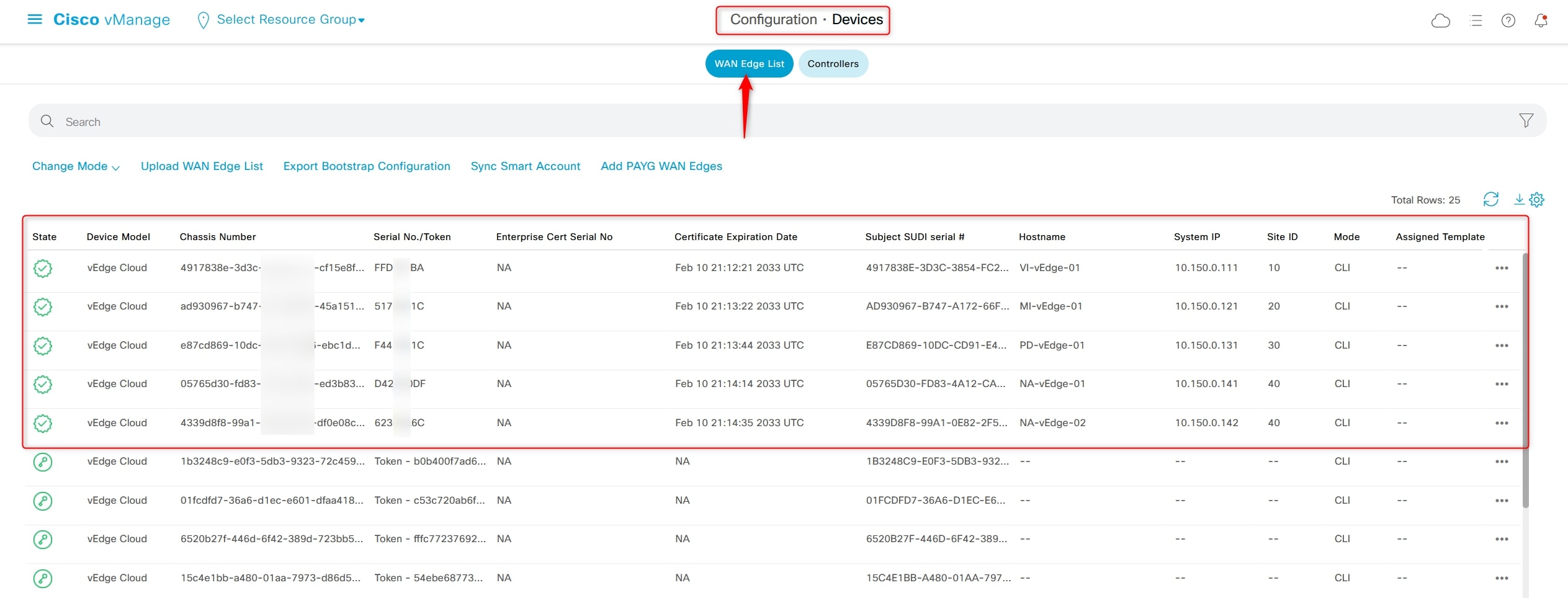
Final check
HERE WE GO!
From GUI main Dashboard this is the output:
Click on “Control Status” in order to verify the devices:
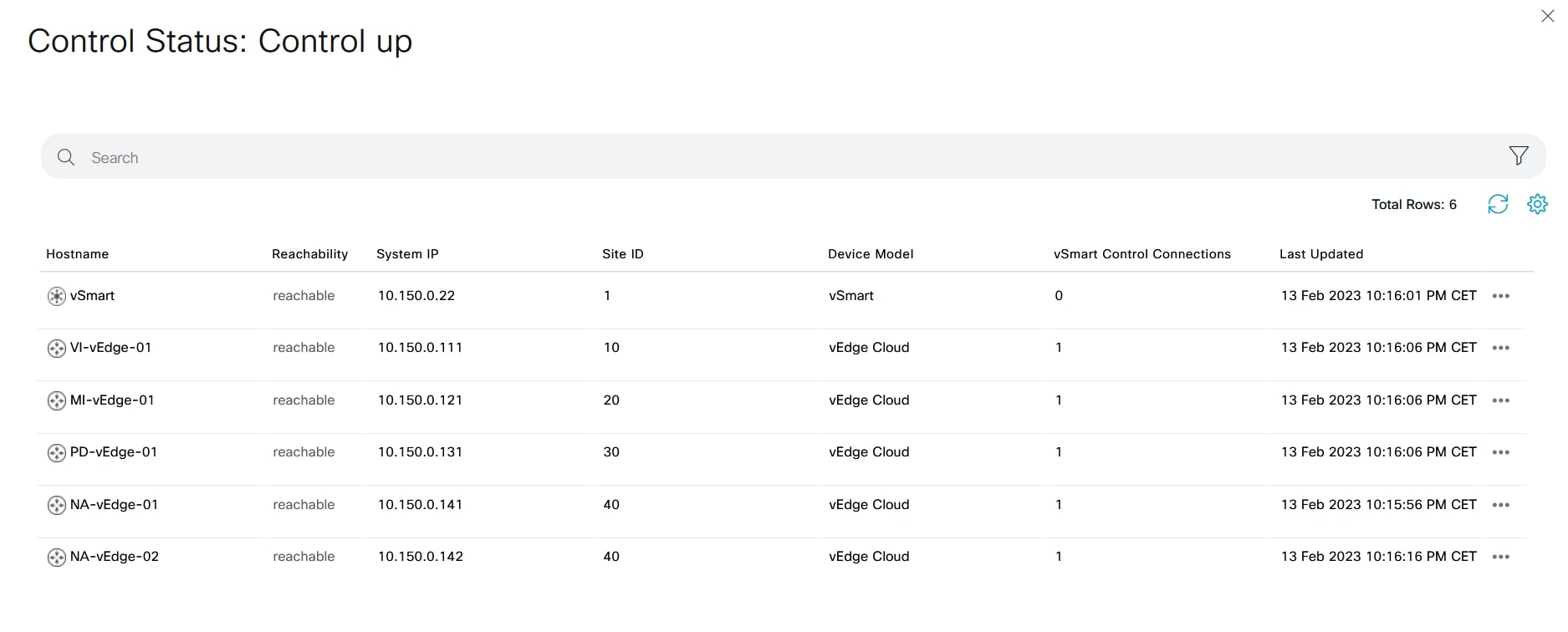
From vSmart CLI use the following commands to see the connections:
show control connections
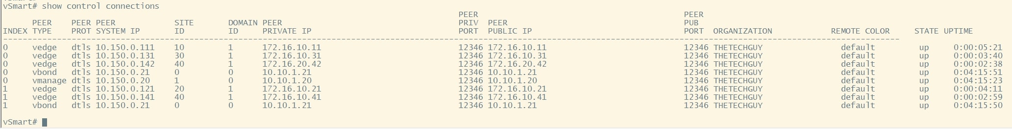
As you can see, all the vEdges are in the list.
Do the same with one of the vEdges:
show control connections

Another interesting command is:
show control local-properties
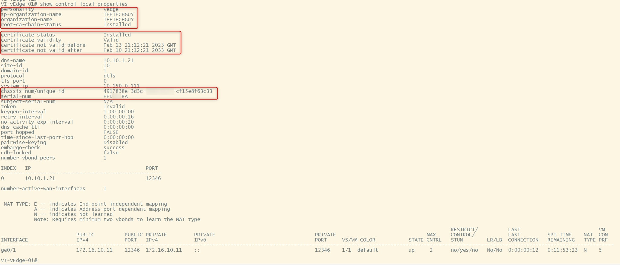
The last thing to do is to verify the BFD session that are active on vEdges. Use the following command to see them:
show bfd session

VI-vEdge-01 has 4 BFD sessions, one for each vEdges in the topology (only 1 transport for the moment). 😉
Congrats! If you complete all the tasks, you should have your lab ready to use 😊
MORE RESOURCES
If you want to test some cool SDWAN feature, here are some interesting step-by-step guides:
- CISCO SDWAN: HOW TO FILTER NETWORKS USING CENTRALIZED POLICY
- CISCO SDWAN: ROUTE LEAKING USING CENTRALIZED POLICY
- CISCO SDWAN: SERVICE CHAINING, FIREWALL INSERTION
- CISCO SDWAN HUB-AND-SPOKE TOPOLOGY!
MENTIONS
Big thanks to Christian and David that helped me in reviewing and fixing this guide. They provided me very useful and insightful tips/suggestions! THANKS
Thanks for your time I hope that you’re enjoying my blog!
If you have some questions, please drop me a message through social networks!😊
👈 You can find the relative icons here on the left of the page
Riccardo